Cart
Your shopping cart is empty!
It's never too late to make things right :)
"The simpler a mechanism is to make by hand, the longer it tends to live. The keyless works proves it: a century and a half of the same idea, still ticking."
— A bench watchmaker's observation
Few assemblies in a wristwatch are asked to do two contradictory things through a single control, and fewer still manage it as quietly as the keyless works — the winding and hand-setting mechanism the old Russian literature calls the remontoir. Through one crown the wearer must be able to wind the mainspring and, when the crown is pulled, to move the hands. The two functions have to be linked to the going train and to each other, yet linked loosely enough that each can be commanded independently. The Pobeda caliber 2602, built at the ZIM works on tooling and a design license that traces back to Fred Lip's French Lip R26, solves the problem with a small handful of stamped parts and a sliding clutch. It is among the most reliable and most easily serviced keyless works ever put into series production, which is precisely why it rewards a close, unhurried look.
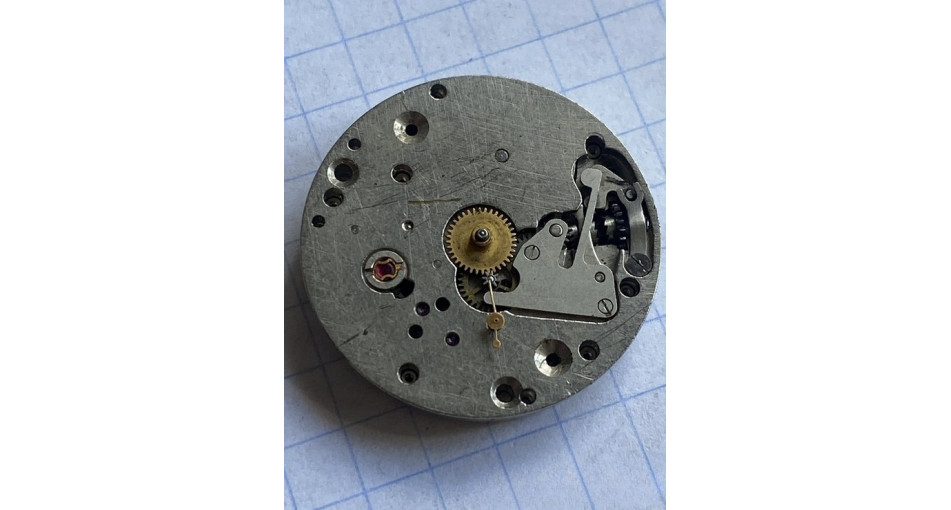
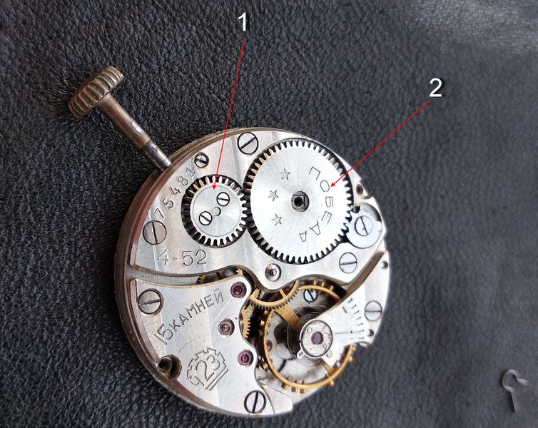
We begin on the dial side. With the hands and dial already removed, the first thing that draws the eye is the hour wheel sitting dead center. Its extended hub — the cannon-shaped tube the watchmaker calls the futor — carries the hour hand and turns once every twelve hours. To get at the works beneath, the hour wheel comes off first.
With the hour wheel gone, the cannon pinion comes into view. This is one of the genuinely clever components in the whole idea of a watch. It carries the minute hand, which completes one turn per hour, but it does a second job as well. The hands can be driven automatically by the going train or manually from the keyless works, so the train, the keyless works, and the motion work all have to be connected — but not rigidly. The cannon pinion is what makes that possible: it is fitted to the arbor of the center (minute) wheel not solidly but with a deliberate slip, a friction coupling. Apply enough torque and the pinion slips on the arbor, letting us place the hands where we choose; left alone, friction holds it so it turns with the center-wheel arbor, carrying the minute hand and, through the minute wheel and its pinion, driving the hour wheel at a twelve-to-one ratio. Because the minute wheel also ties into the setting wheels, that single friction joint is the hinge on which both modes turn. Beneath a spring cover sits the rest of the assembly, which we are about to expose.
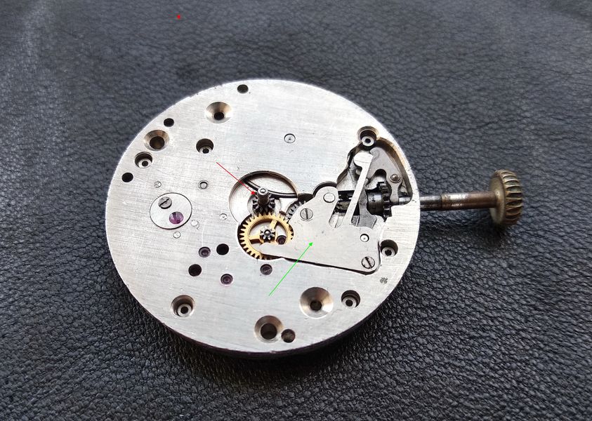
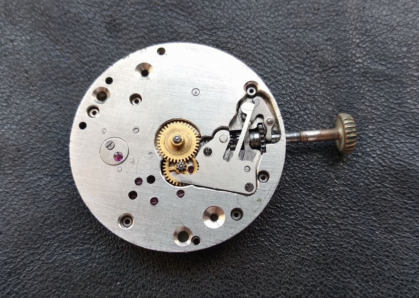
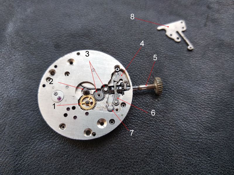
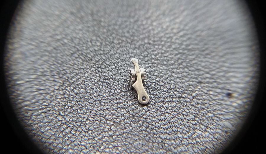
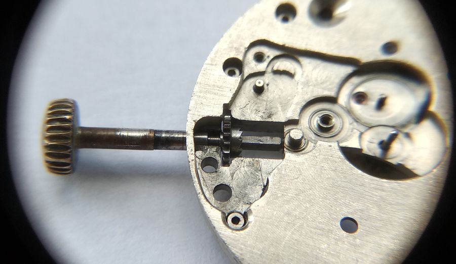
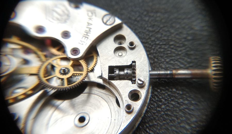
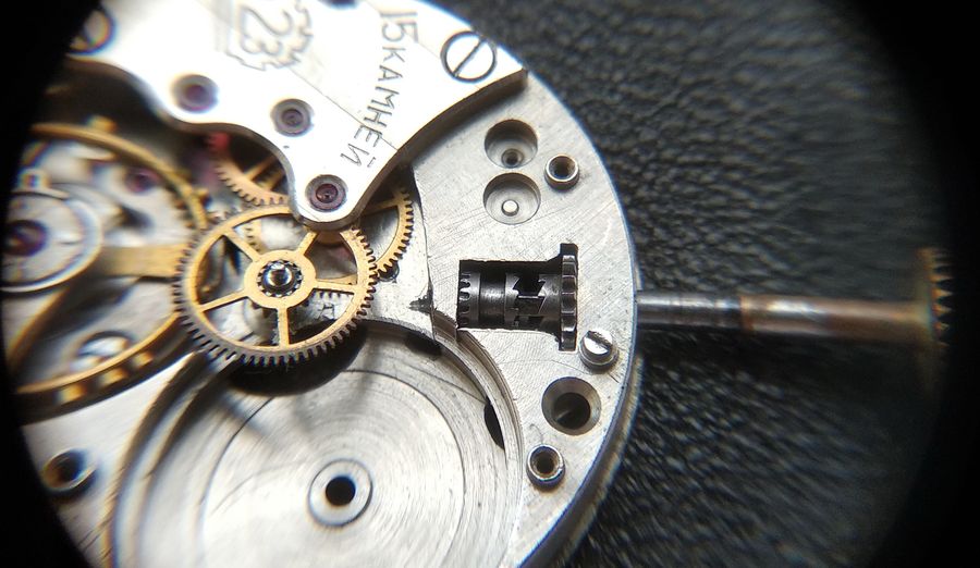
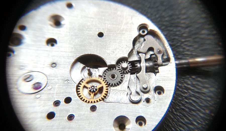
With the cover off, the whole keyless works is in front of us. The principal parts are: the minute wheel of the motion work; the cannon pinion; the setting wheels; the intermediate setting lever, also called the yoke, which is driven directly by the stem; the winding stem itself; the setting lever that bears on the sliding clutch; the R-shaped setting-lever spring; and the spring cover that holds it all down. Beneath the setting lever lies the sliding clutch — the heart of the remontoir — which we will dismantle and examine in detail shortly.
Two more parts belong to the winding side proper: the crown wheel and the ratchet (barrel) wheel together with the barrel click. A note on terminology is in order. In modern movements the so-called crown wheel is no longer a true crown wheel — it no longer carries the ring of side-facing teeth that the earliest movements used — but the name has stuck because it became familiar. A genuine crown wheel is a special type whose teeth stand on its side face; it meshes either with an ordinary spur wheel or with a lantern of pins. We will return to this distinction further on, where it matters.
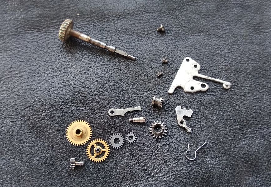
Now we strip the remontoir down to its individual components.
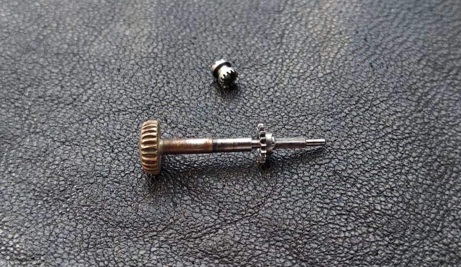
Here is the arbor of the center, or minute, wheel — the very post onto which the cannon pinion is pressed with its measured friction. Everything in the motion-work hierarchy hangs off this slip fit.
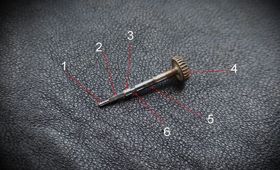
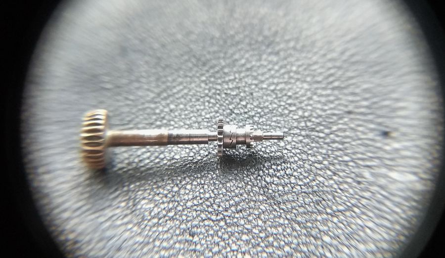
Let us study the parts in detail, beginning with the winding stem. Its layout is practically identical across all hand-set watches, differing only in size. It comprises: the tail; the square; the cylindrical section, or shoulder; the crown seat; the axis; and the groove for the intermediate setting lever. The tail locates the stem in its seat in the main plate. The square section couples the stem to one half of the clutch — the castle, which the trade nicknames the "barrel." On the shoulder, the cylindrical part, rides the other half: the winding pinion, sometimes called the "half-barrel." For so plain a part, it carries a surprising amount of responsibility.
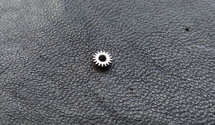
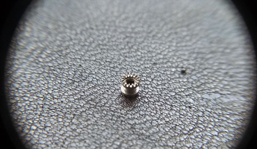
How is the sliding clutch built? Start with the winding pinion, the "half-barrel." It has a standard gear rim around its edge that engages the crown wheel, a round bore that seats it on the stem's shoulder, and — on its side face — a ring of saw-tooth ratchet teeth that mate with a matching ring on the castle.
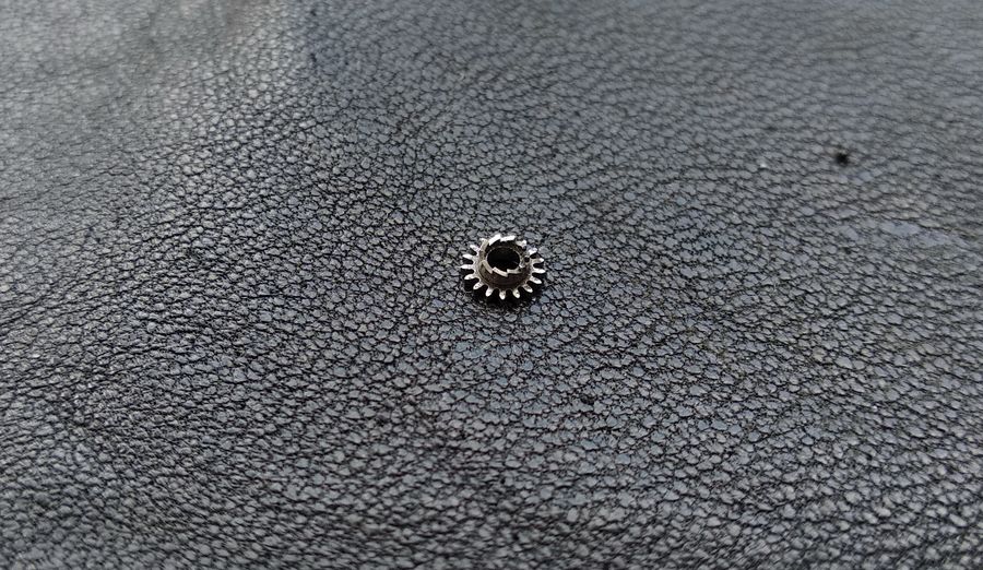
Turn it over and the reverse face is plain and smooth — nothing engages on that side.
Onto the stem the winding pinion goes like this: its seat is the shoulder, the cylindrical part that serves as its axis. The pinion spins freely there and is connected to the stem in no other way.
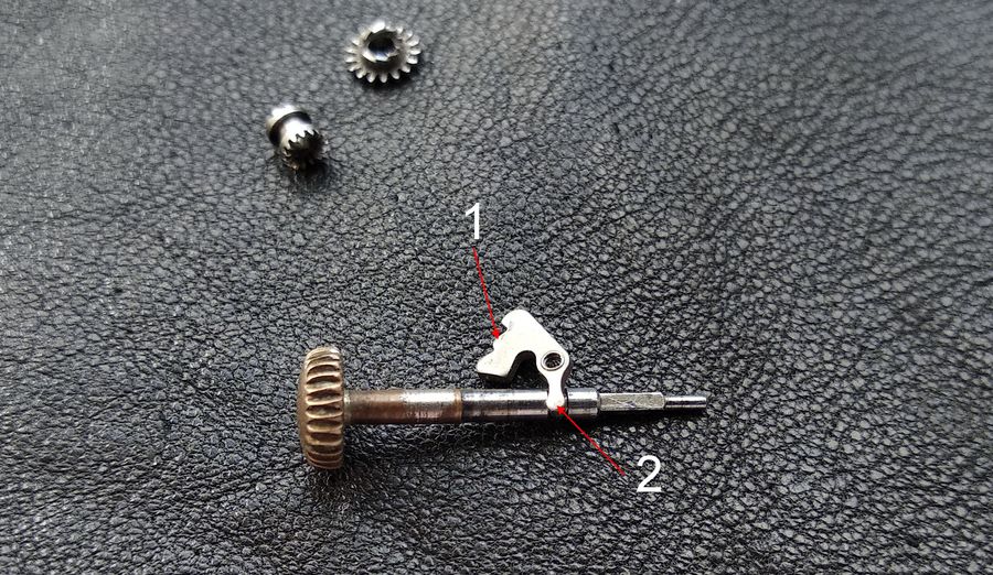
Now to how the intermediate lever interacts with the stem. The lever carries a small tab that drops into the groove on the stem; this is what anchors the stem to the plate and limits its travel along its own axis. Recall the familiar "magic button" we press to release the stem from a movement: pressing it lifts the lever, the tab comes out of the groove, the stem is uncoupled, and it is now free to slide out. There is not always a button. In our case there is a screw instead; loosen it until the lever's tab clears the groove and the stem can be withdrawn. The lever itself has a comb and side pusher, and the tab.
Now the second half of the clutch — the castle, the "barrel." It is an important part and deserves attention. On it are the ratchet ring and the crown rim. Around its waist runs a groove for the setting lever.
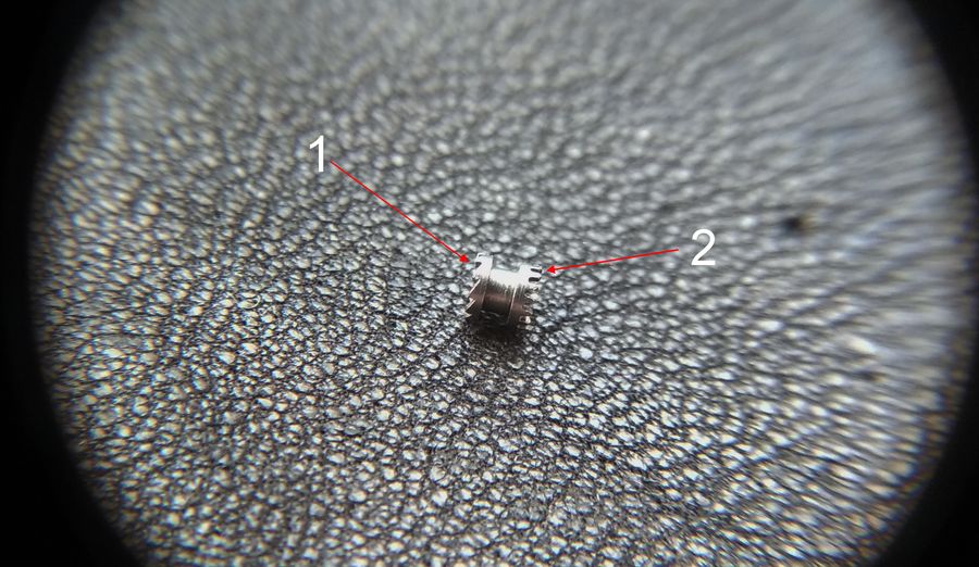
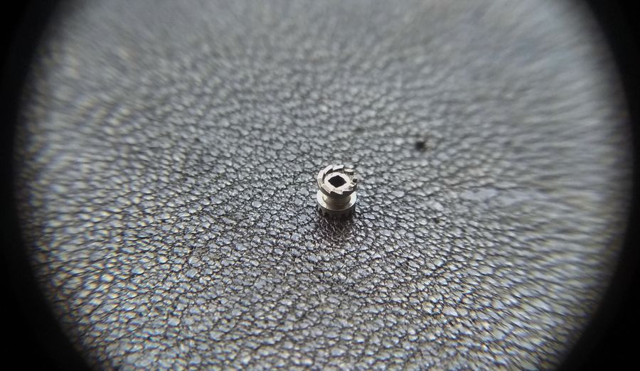
From this angle the ratchet ring is clearly visible — the counterpart to the one on the winding pinion — along with the square tunnel that seats the castle on the square section of the stem.
This is the crown end of the castle, the part that mates with the system of setting wheels.
And this is how the setting lever fits into the castle's groove.
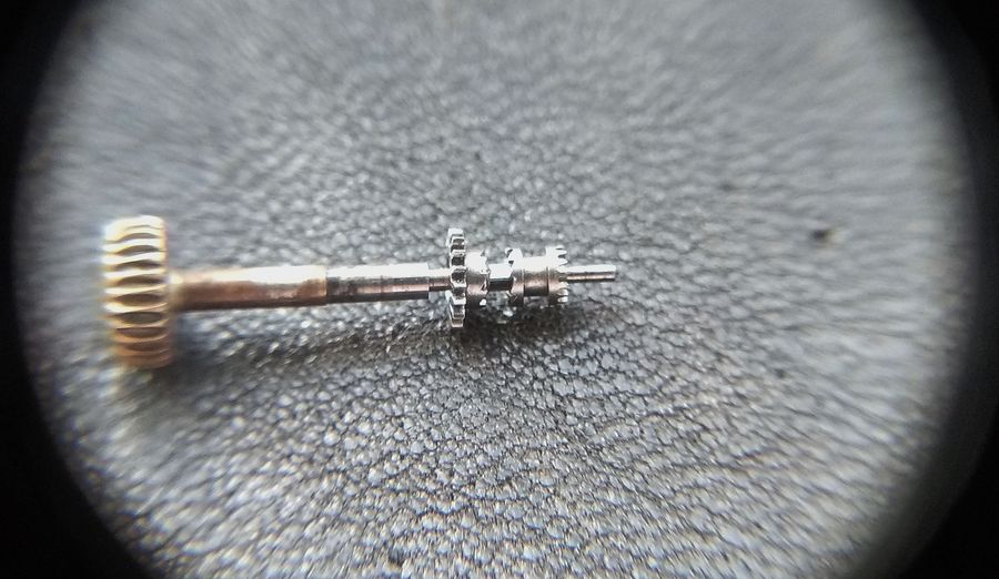
Let us assemble the clutch on the stem. The winding pinion sits on the shoulder, the castle on the square section. In this position the clutch is in winding mode: the ratchet rings are closed together. Now turning the stem clockwise carries, through the engaged ratchet, the winding pinion and from there the crown wheel. Turn the stem counterclockwise and the ratchet rings ride apart, so the pinion does not turn. We will come back to this behavior once the remontoir is reassembled.
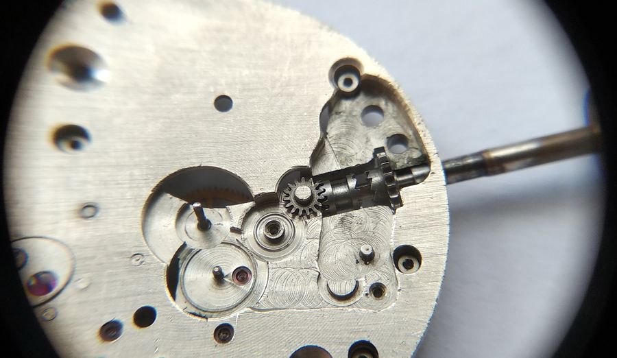
And what happens if we slide the castle away from the winding pinion? The castle moves, its crown end comes into mesh with the setting wheel, and the turning effort is now passed to the setting wheels, the minute wheel, the cannon pinion — and the hands are set. We will see this even more plainly below.
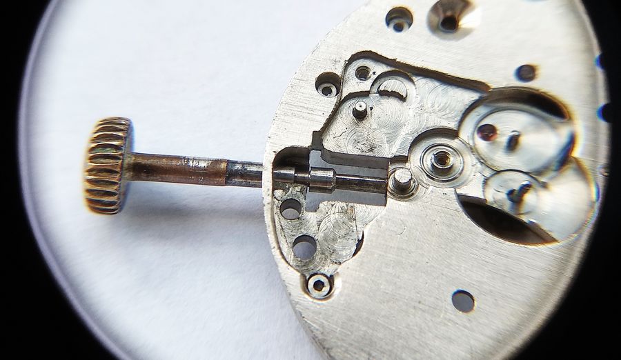
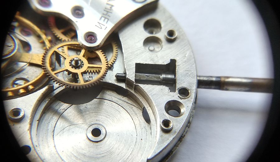
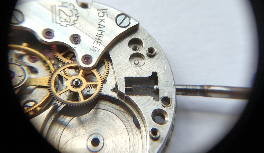
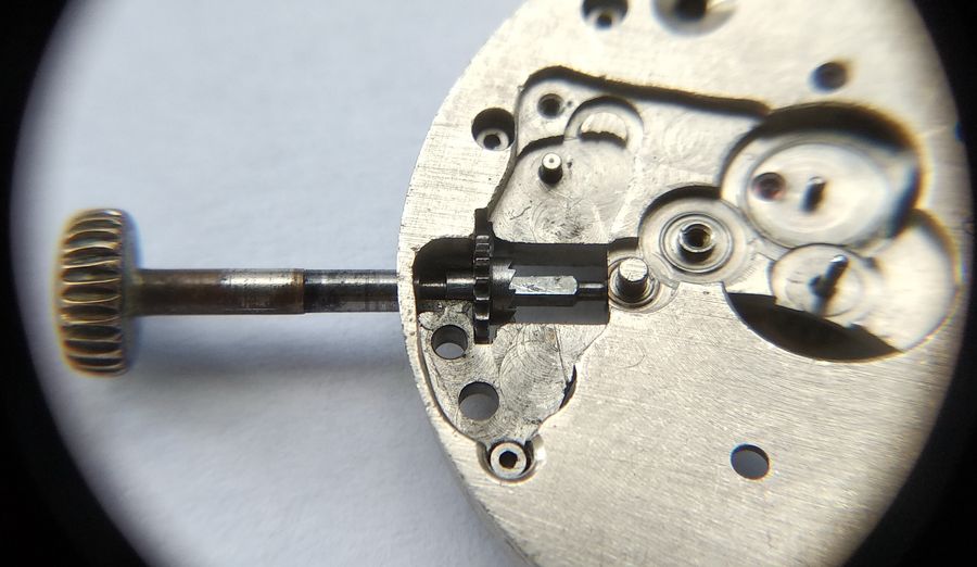
Now to how the winding stem sits in the main plate. Here the stem is pushed home, in the winding position.
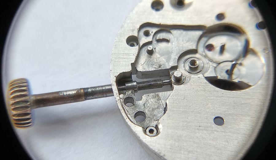
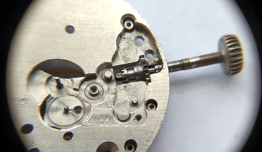
And this is the hand-setting position.
Seen from the reverse side of the plate, this is the winding position.
And the setting position. Notice that the stem's tail travels in a tunnel, now emerging from it, now hiding within. In some watches this movement is harnessed for a stop-seconds function: the tail presses on a spring that arrests either the balance, as in the "Sportivnye," or one of the train wheels. This movement is not provided for in the caliber before us. Here the stem stands in setting mode.
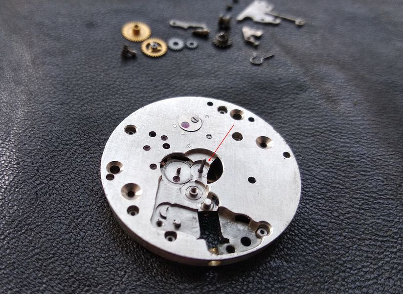
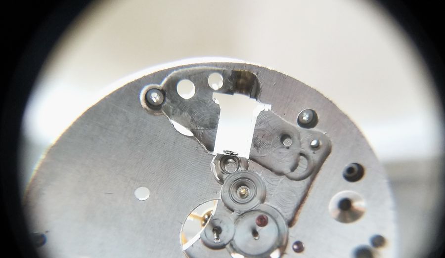
This is the T-shaped recess in the plate in which the clutch is mounted. In the cross-bar of the T sits the winding pinion, and the seat denies it any axial movement. In the larger pocket sits the castle, and that seat allows it to slide along its axis. The geometry of the recess, in other words, is what decides which member of the clutch may move and which may not.
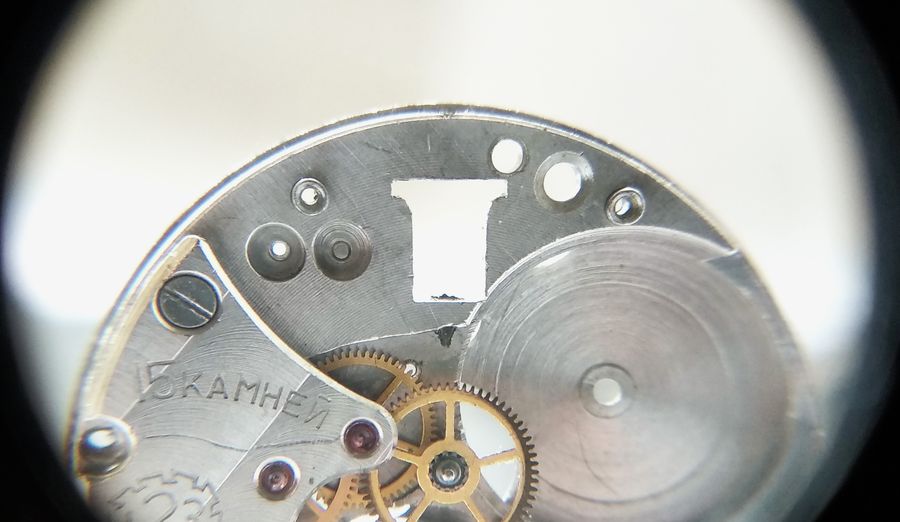
And the same recess from the reverse side.
Let us look at the winding pinion's installation. Here the stem is in winding mode.
And here in setting mode. As we see, in either stem position the winding pinion stays exactly where it is — for otherwise, how could it keep its mesh with the crown wheel?
Now we assemble the clutch in full. Here it is in winding mode, and the meshing of the ratchet teeth is plain to see. Turn the stem clockwise and the winding pinion follows it. Turn it counterclockwise and the ratchet rings part. What keeps the clutch from parting during winding is the setting lever and the R-shaped spring — something we can observe once everything is assembled.
And what happens when the clutch moves to setting mode? The castle slides until its crown end engages the setting wheel. The winding pinion drops out of the ratchet and can no longer turn. Instead, stem rotation passes through the square and the castle keyed to it, and on to the hand-setting train.
This is how the process looks from the reverse side of the plate, in winding mode.
And in setting mode.
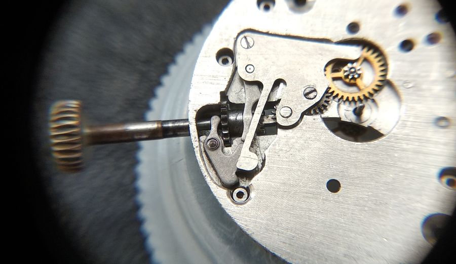
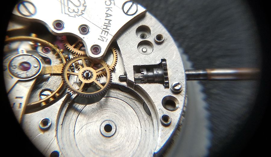
How is the switch between modes actually made? By a system of two levers and the R-shaped spring. This arrangement is virtually the same in nearly all wristwatches, mechanical and electromechanical alike, wherever hands are used to indicate the time. There are variations in execution, of course, but the principle does not change. We install the intermediate and setting levers in place. The spring, unfortunately, cannot be fitted without the cover or it springs free — and with the cover on we would see nothing. So we follow the switching action without the spring. Here the levers and clutch are in winding mode: the stem is pushed in, the intermediate lever is turned to the right, clockwise, and the faces of the levers' pushers are aligned. In this position the setting lever is held by the force of the R-spring.
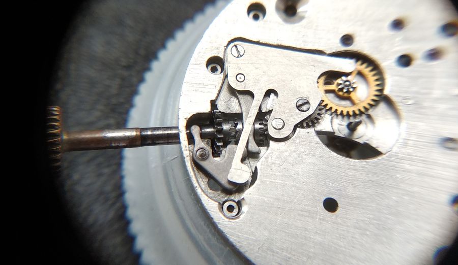
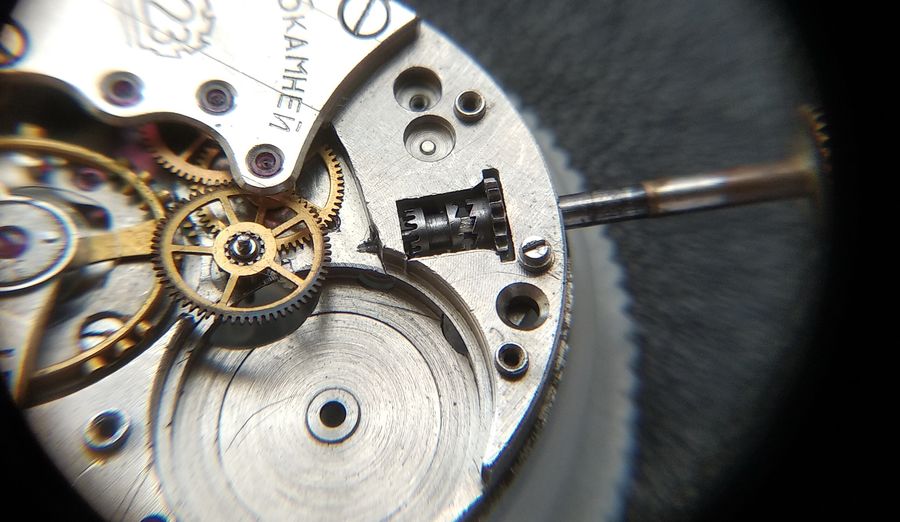
Now let us shift the remontoir into setting mode by pulling the stem outward. What do we see? The stem swings the intermediate lever to the left, counterclockwise, by the tab that sits in the stem groove and is held there by the retaining screw — held, but still free to pivot. The intermediate lever's pusher face acts on the setting lever's pusher, and the setting lever shifts to the left in the photograph, dragging the castle of the clutch with it by its groove. The clutch moves, the winding ratchet uncouples, and the castle's crown end engages the setting wheel. With the remontoir fully assembled, the switch positions are held by the interaction of the intermediate lever's comb and the finger of the cover spring — which we will see below.
If we now return the stem, pushing it home, the setting lever — under the R-shaped spring — returns the castle to the winding position. Now it is plainly visible what happens when, in winding mode, the stem turns counterclockwise: the clutch ratchet uncouples, but under the R-spring it strives at once to close again. It is exactly this that produces the characteristic clicking we hear on the reverse turn of the crown. On the forward turn there is rapid clicking too, but that comes from the barrel-wheel click, and it is faster because the barrel wheel has more teeth.
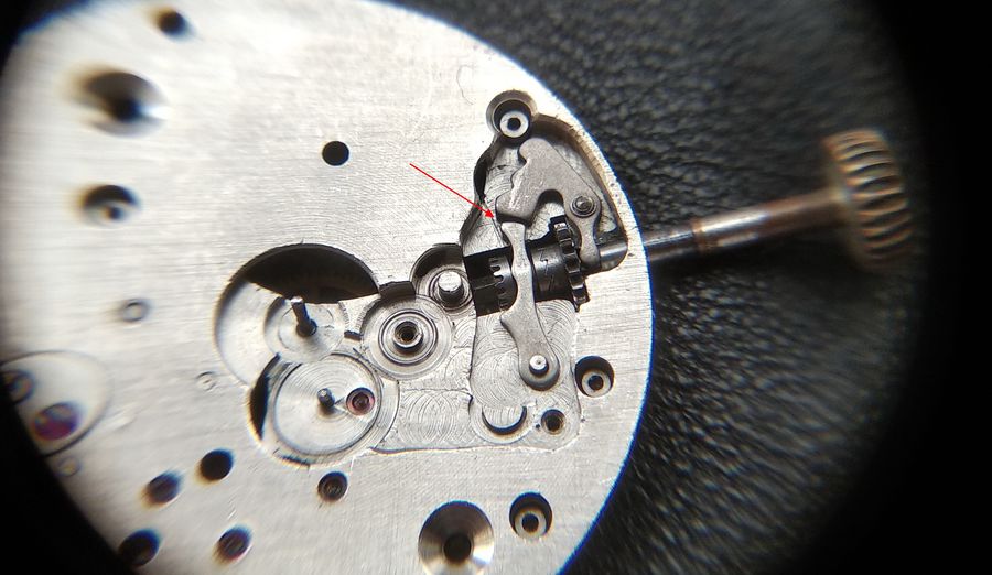
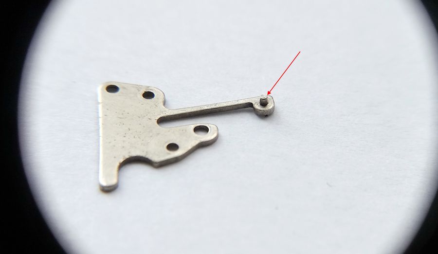
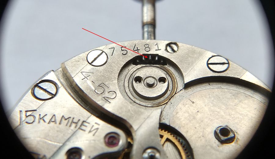
This is the spring cover of the remontoir. The red arrow points to the spring finger, which works against the intermediate lever's comb and fixes the two switch positions — winding and setting.
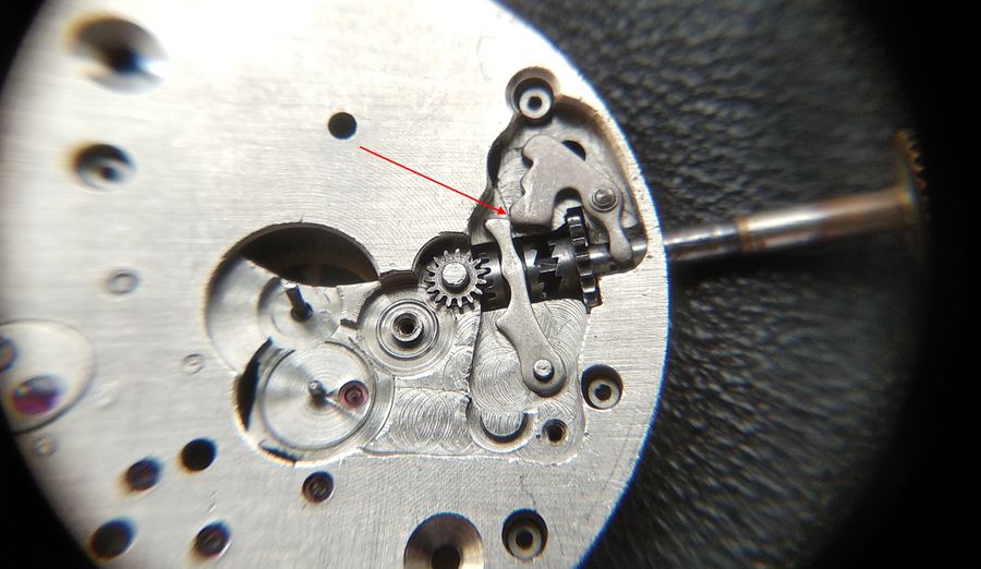
Now cover the remontoir. The interaction of the spring and the intermediate lever's comb is clearly visible. This is how it stands in winding mode.
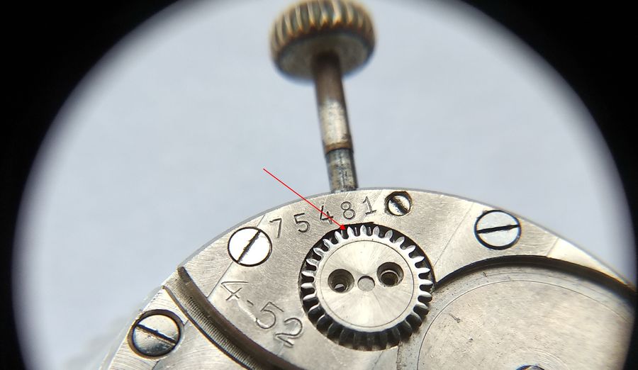
And this is setting mode.
Winding mode from the reverse side.
And setting mode.
Now we set the barrel bridge. In the bridge, next to the seat for the crown-wheel rim, a recess is cut into which the rim of the winding pinion enters.
We set the crown wheel in place and see how the teeth of the crown wheel and the winding pinion fall together. Now the effort from the winding pinion passes to the crown wheel, from the crown wheel to the ratchet (barrel) wheel, and the barrel click guards the wound spring against running back. This is how the mainspring is wound by hand.
In closing, it is worth describing a few of the typical faults that turn up in the remontoir. The assembly is reliable and stable — so much so that repairers often skip dismantling and servicing it altogether — yet a handful of problems do occur.
One is destruction of the teeth on the winding pinion's ratchet ring. The symptom is a felt skip at the stem when winding, and a mainspring that will not wind. Another is wear in the plate's seat for the winding stem: the stem drops, the intermediate lever may no longer hold it, the stem begins to fall out, and the winding pinion comes out of mesh with the crown wheel — again, the "catching" sensation when winding. When the movement is dirty or poorly lubricated, the setting lever fails to carry the castle to its extreme positions; the result is either hands that cannot be set, or a stem that skips while winding. Faults of this order are quite rare, but they do happen, which is why preventive attention to the assembly during a full service is well advised — especially when winding or hand-setting already feels wrong.
A separate word about the fit of the cannon pinion. Its slip torque must be set so the hands follow the center-wheel arbor confidently, yet it must never exceed the holding force of the spring on that arbor — otherwise the pallet fork can be damaged during hand-setting. So if the effort needed at the stem to set the hands has visibly risen or fallen, the watch should go to a workshop. And unless the instructions say otherwise, set the hands in the direction of their travel, with the mainspring wound.