Raketa Caliber 2609B: Service, History, and the 21-Jewel Baltika Movement
Raketa Caliber 2609B: Twenty-One Jewels and the Road to the 2609.NA
Raketa Caliber 2609B: Twenty-One Jewels and the Road to the 2609.NA
"Let things have been as they were — for somehow they were. Never was it so that there was nothing at all." — Yaroslav Hašek
Anyone familiar with the Raketa 2609.NA — referred to in Soviet technical literature and among collectors as the "Flat Russia" series — will likely have wondered what the Petrodvorets factory was producing before that caliber came into being. The question is a reasonable one. The 2609.NA represents a genuine high point in Soviet mechanical watchmaking: a systematic, serviceable movement engineered with a discipline that few contemporary domestic calibers matched. Nothing of that quality appears without precedent. Before the 2609.NA there was the 2609B "Baltika," and before that the more fundamental 2603. Understanding this lineage explains why the later design made the particular choices it did.
The earliest Raketa movements produced with any documented consistency were built on the 2603 caliber — a direct evolutionary step from the 2602 ZIM, the movement that powered the Pobeda. Two shortcomings limited the 2602 in service. First, the balance staff ran without any form of anti-shock protection, making the movement vulnerable to impact damage at the balance pivots. Second, the center wheel pivot ran without a jeweled bearing, bearing instead in brass — a condition that shortened the service interval and produced progressive wear at a critical point in the going train. The 2603 corrected both. An Incabloc shock-absorption system was installed for the balance, mounting each bouchon in a spring-loaded cradle that could deflect under impact and return the balance staff to its seating. A jewel was fitted to the barrel bridge to support the upper center wheel pivot, raising the total count to sixteen. These changes extended the service interval measurably and improved resilience under everyday wear. The caliber established a solid reputation, and Raketa watches built on it sold in volume. On the strength of that commercial position, the factory pursued a parallel development — the Rekord 2209 — but that effort proved to be a costly detour.
Raketa 2603 and the Rekord 2209 Interlude
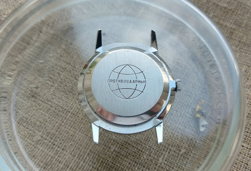
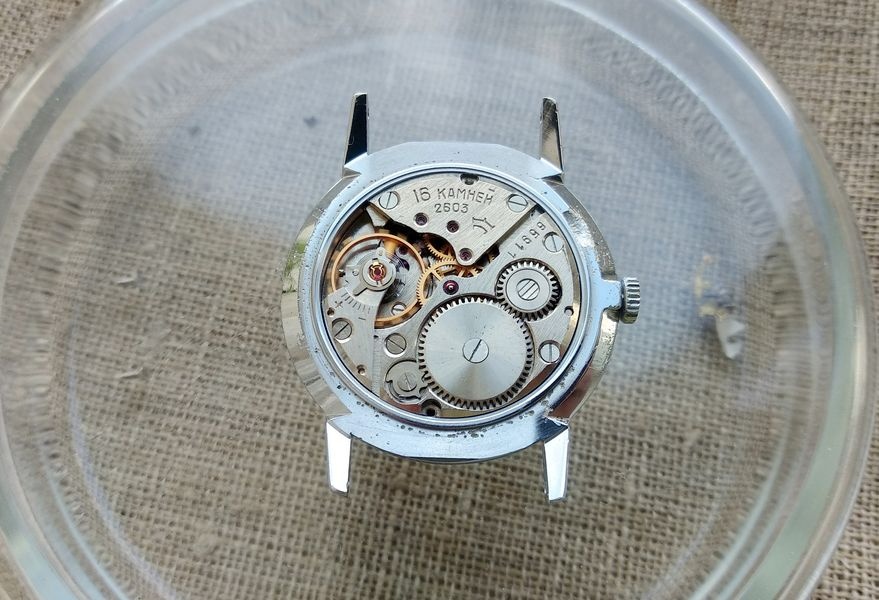
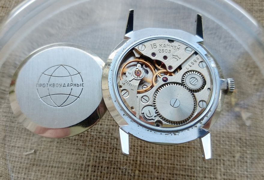
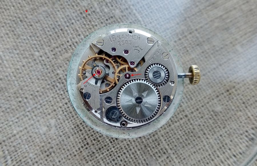
The case back of a Raketa on caliber 2603, bearing text that advertises the movement's shock-resistant properties. The 2602 ZIM had offered no such protection; this marking represents a genuine engineering improvement rather than a marketing formality. The layout closely follows the 2602 ZIM baseline; the meaningful changes are structural rather than visual. Parts interchangeability with the older caliber is partial only — the engineering logic is shared, but the execution at critical points differs.The 2603 from the movement side. The family resemblance to the Pobeda-derived caliber is clear, but the additions — shock protection at the balance and a jeweled center wheel bearing — distinguish it from its predecessor at the level of practical performance.Arrows mark the two defining improvements of the 2603: Incabloc shock-absorbing bouchons at the balance assembly, and a jeweled pivot bearing for the center wheel in the barrel bridge. The jewel count reached sixteen. The balance jewel count itself was unchanged from the 2602; only the method of mounting shifted to the anti-shock configuration.
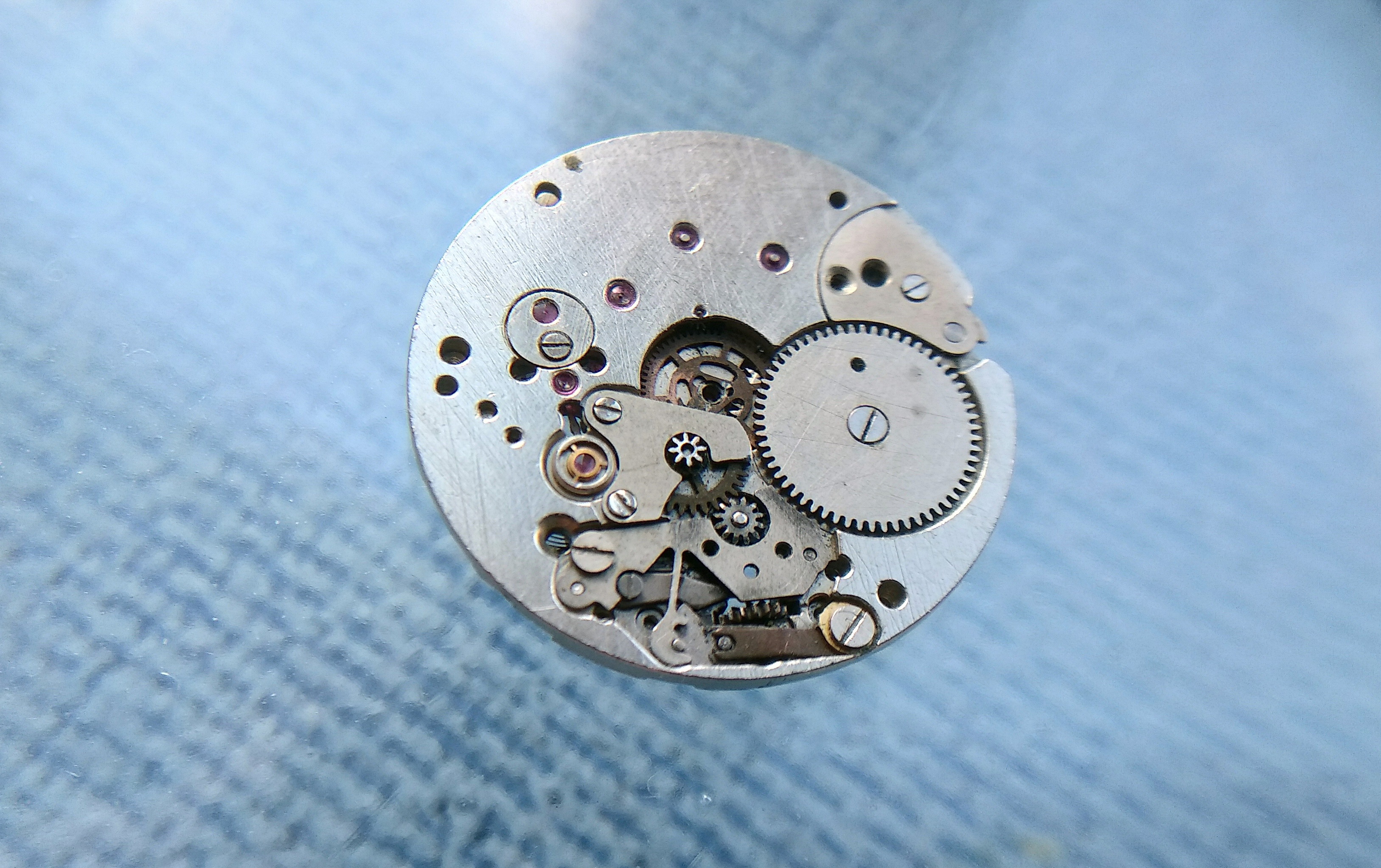
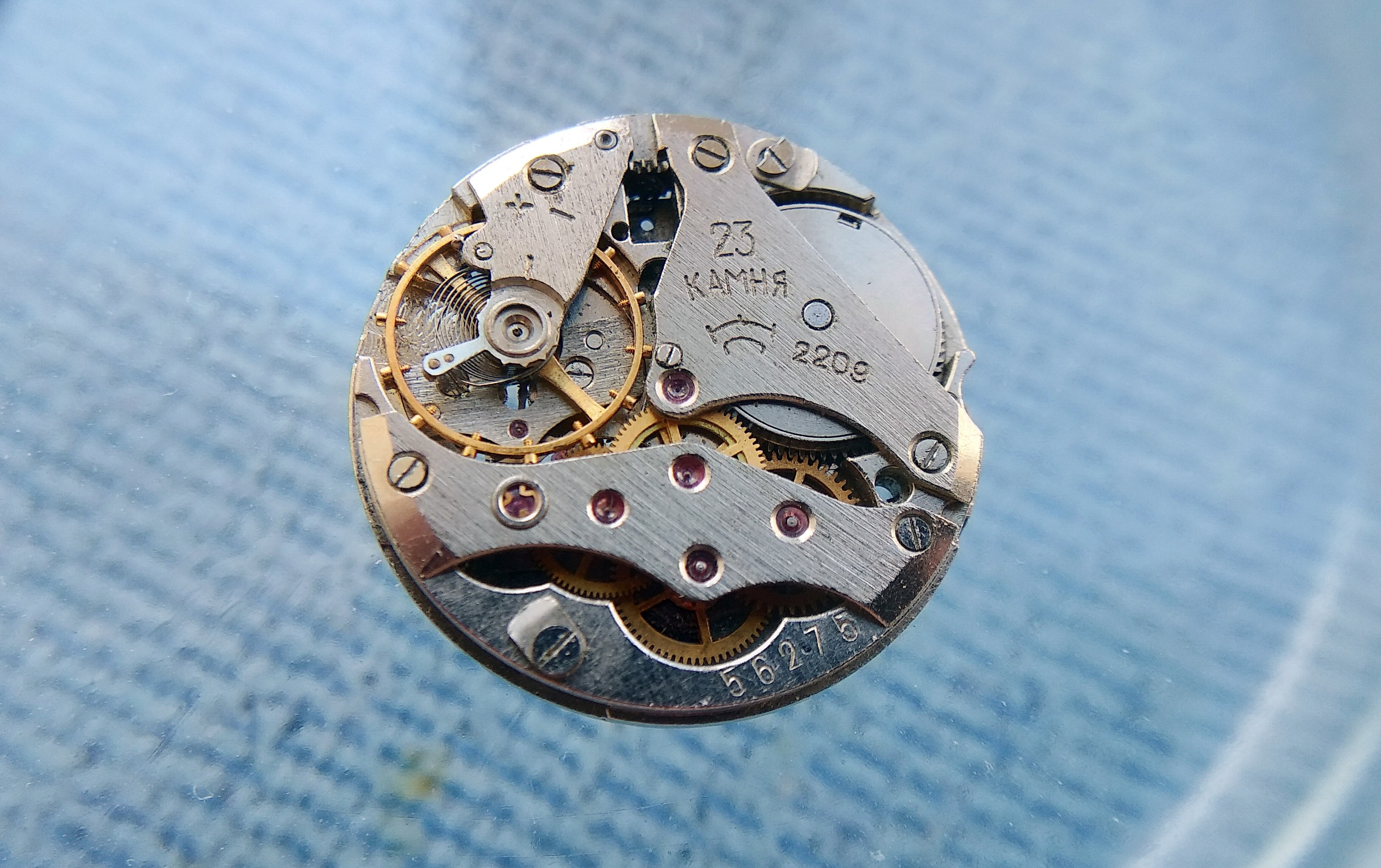
The Rekord 2209 occupied a parallel branch of the factory's engineering effort. A 23-jewel caliber measuring 2.7 mm in height, it was exhibited at the Leipzig international trade fair in 1965 and attracted favorable attention for its ambition. In production, the movement proved almost ungovernable in service. Workshop technicians coined an unflattering designation for it — a name suggesting that any intervention tended to scatter components across the bench. Five wheel arbors shared a single bridge; the hairspring was extremely fine and prone to contacting adjacent surfaces if displaced even fractionally from plane; the keyless works incorporated an arrangement peculiar to this caliber that added further complication. The factory eventually attached an automatic winding module to the 2209, but this addition failed to establish the movement as a platform suitable for systematic production. It was discontinued. Surviving examples continue to function — an unlikely tribute to the movement's underlying quality — and they remain of interest to collectors. As a foundation for a production family, however, the 2209 was simply impractical.
The Raketa Rekord 2209 — 2.7 mm thick, 23 jewels, Leipzig 1965. The five-arbor bridge arrangement that enabled its remarkable thinness made every service operation a test of patience. What the exhibition stand presented as an achievement, the repair bench experienced as an ordeal.A second view of the 2209, showing the rotor attachment that the factory added in an attempt to extend the caliber's commercial usefulness. Neither the automatic module nor the caliber's intrinsic qualities were sufficient to overcome the movement's fundamental unserviceability in field conditions.
The 2609 Series: From Basic Caliber to Twenty-One Jewels
Market demand for a movement with a center seconds hand, built on a contemporary engineering foundation, drove the development of the 2609. The designation followed the nomenclature standard then in force: "26" identified the plate diameter at 26 mm, and "09" specified a center seconds configuration. The earliest 2609 movements, produced before any letter suffix was applied, used through-jewels alone for the gear train pivots. Subsequent engineering refinements added overlay cap jewels — placed over the upper pivot holes of the escapement wheel and intermediate wheel — which improved oil retention at those positions and extended the lubrication interval between services. This modification raised the total jewel count to twenty-one.
The factory's technical marking convention for such changes is worth noting. When a caliber was modified solely to increase the jewel count, the suffix was written as a decimal point followed by the letter "К" (for камни — stones) and the number of jewels added. Under this system, the 2609B was also designated 2609.К5, indicating that five jewels had been added to the sixteen of the base 2609. The 2609A preceded the 2609B; the practical distinctions between the two sub-variants are marginal. Both carry overlay jewels on the escapement and intermediate wheel bridges. Both use a fixed regulator pin column — a design detail that would change in the 2609.NA, where the column became adjustable, giving the regulator a true locking action rather than relying solely on friction.
When examining the 2609A and 2609B in detail, a persistent sense of recognition emerges for anyone familiar with Swiss caliber archives. Cross-referencing the design against period documentation points to at least a visual kinship with the MST 414 produced by Roamer — a movement of roughly the same era. Whether this represents direct inspiration, parallel engineering convergence, or a more formal connection is difficult to determine at this remove. The resemblance is, in any event, notable enough to document.
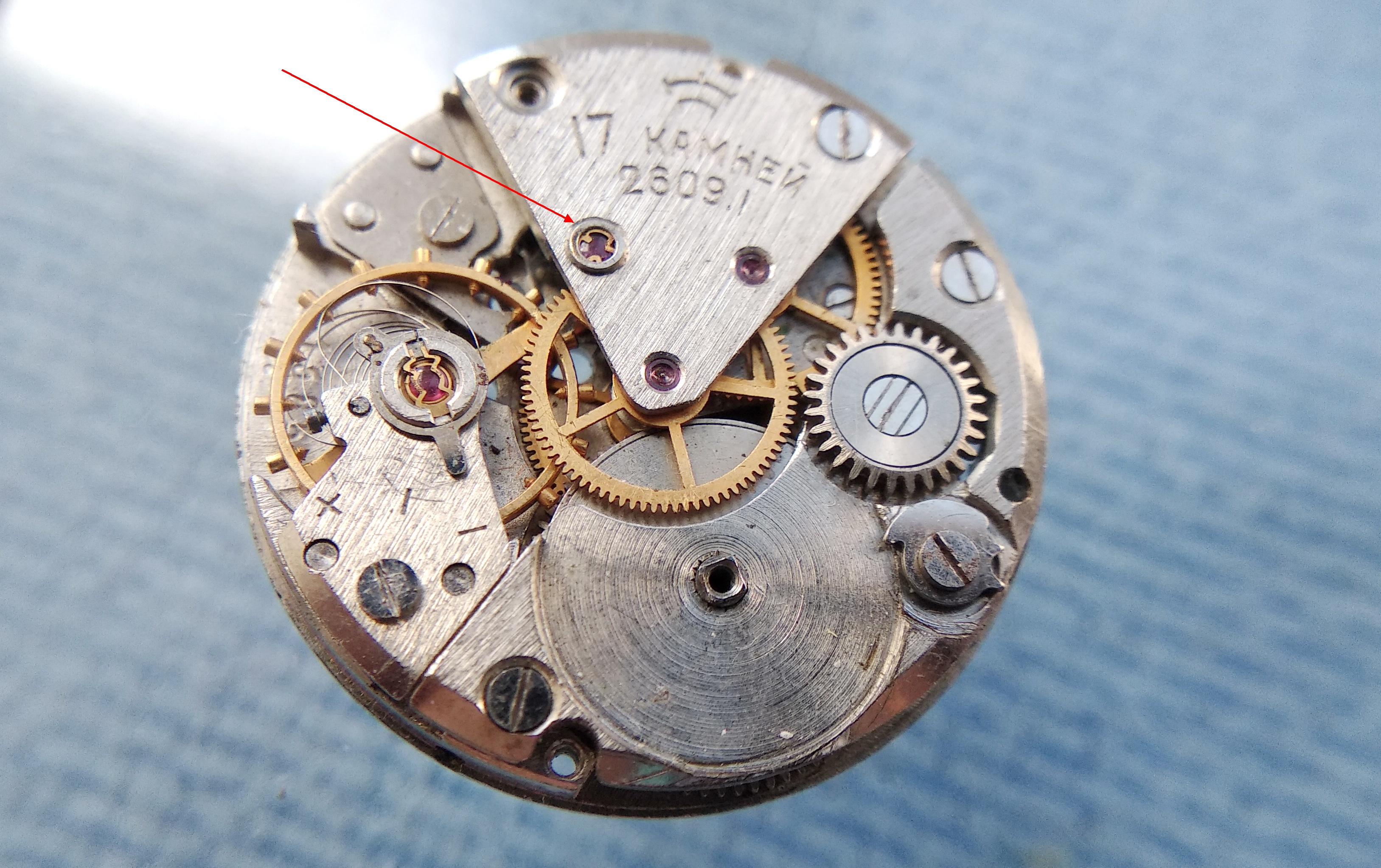
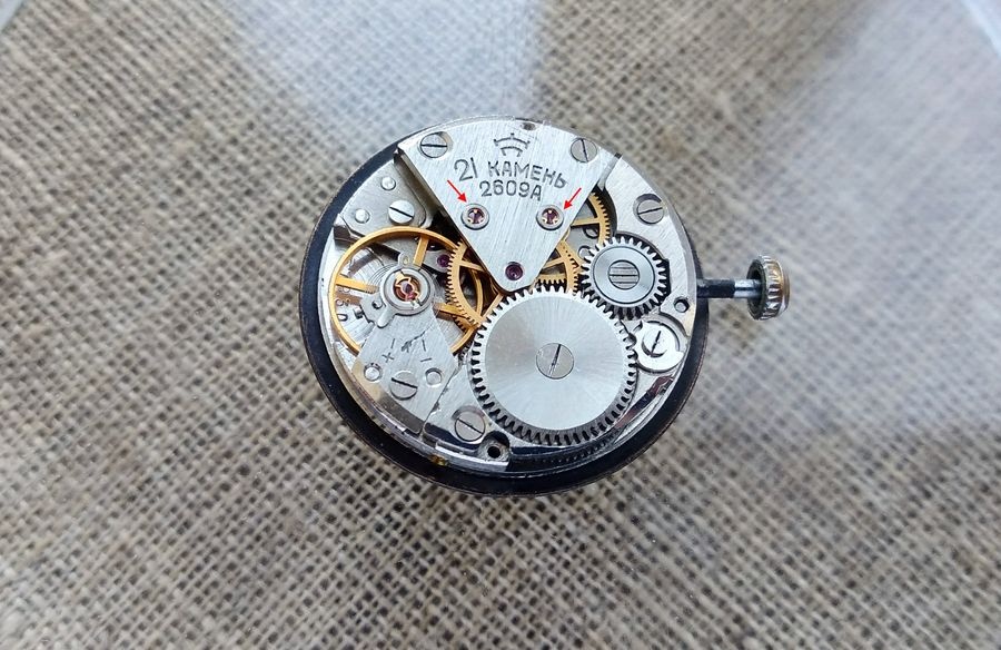
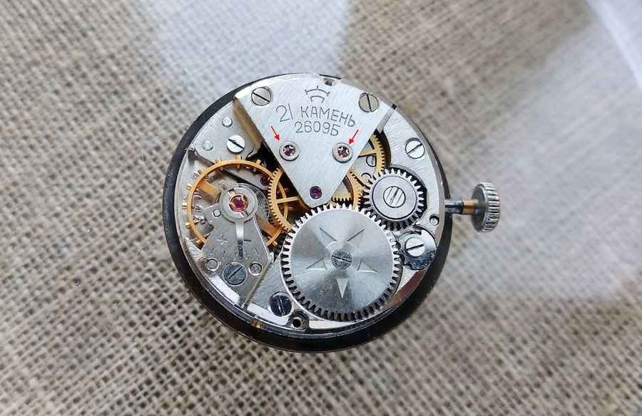
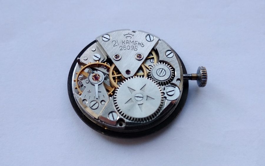
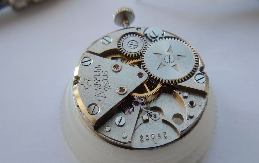
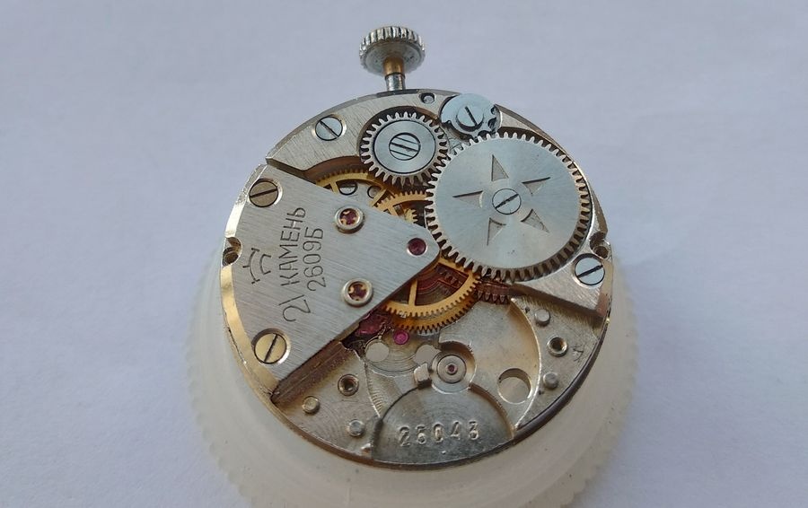
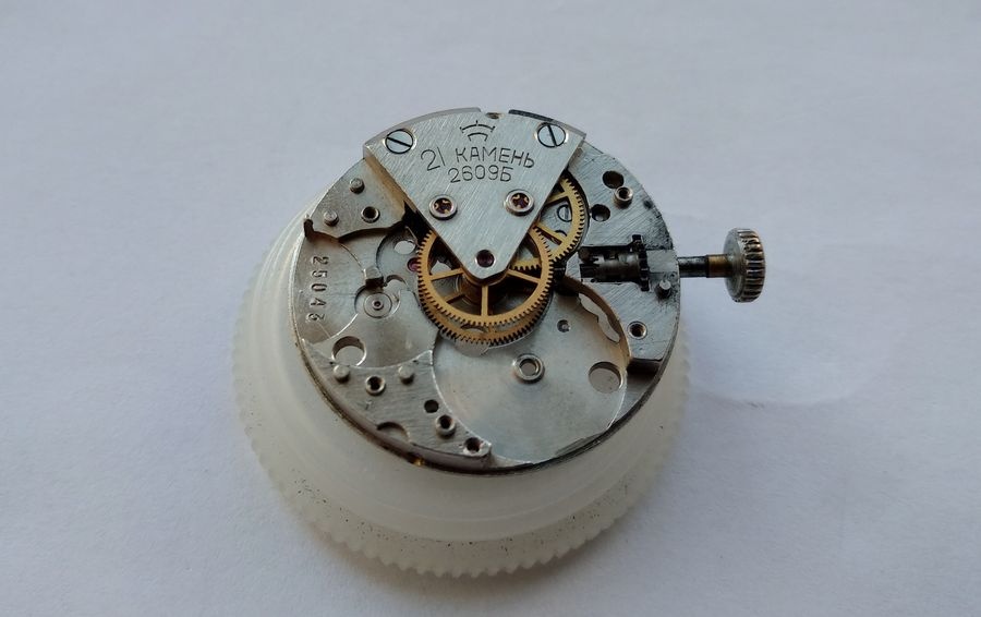
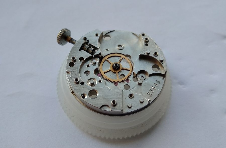
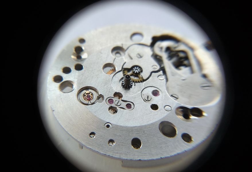
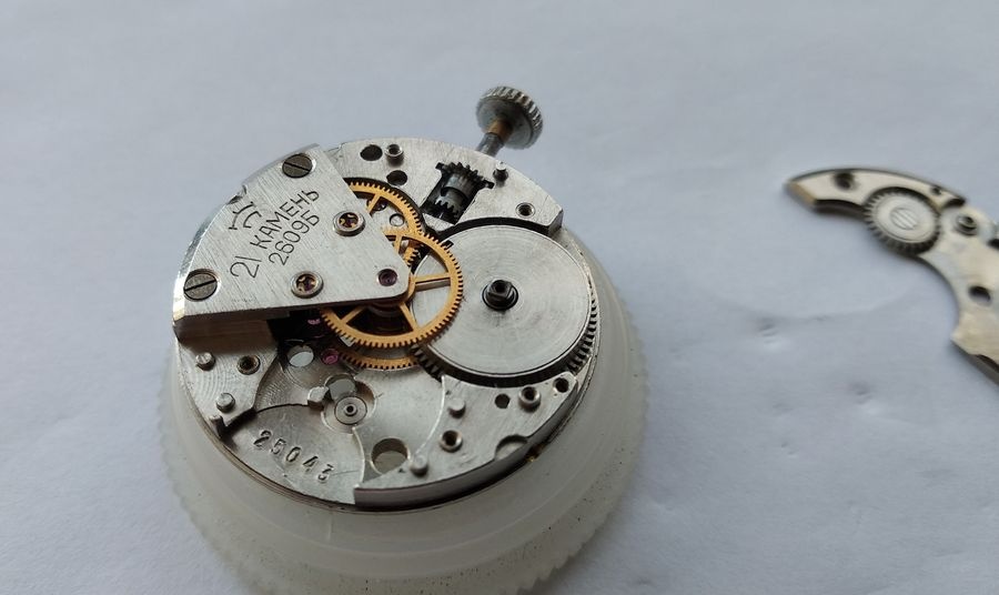
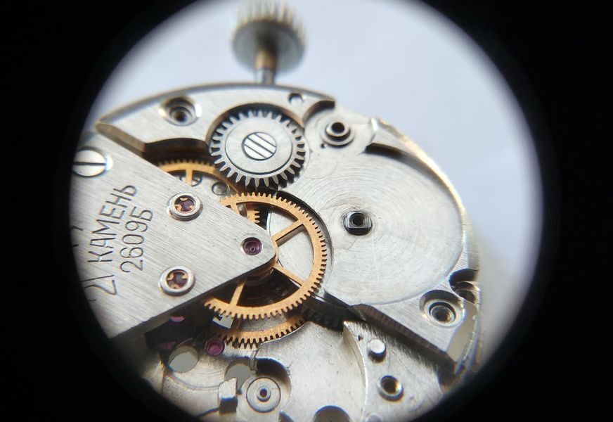
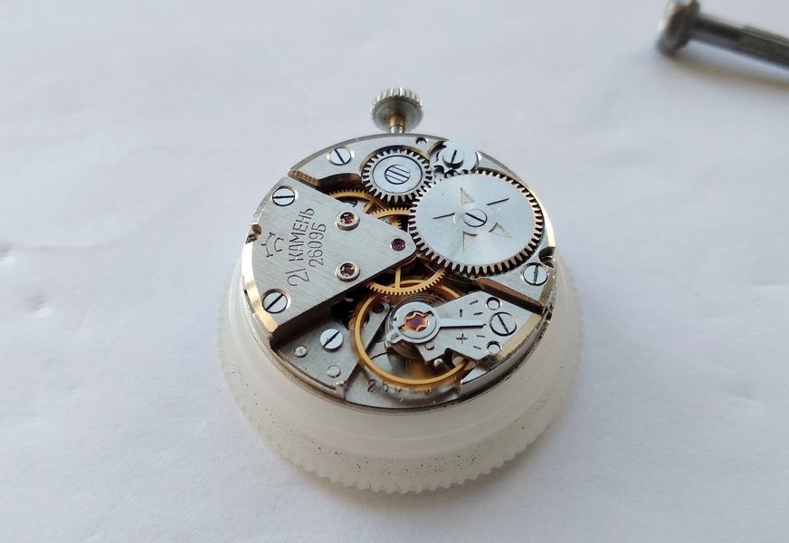
Caliber 2609.1: the transitional configuration, with a single overlay jewel at the escapement wheel pivot bearing. This intermediate step preceded the complete twenty-one jewel arrangement established in the A and B sub-variants.Caliber 2609A with overlay jewels on both the escapement wheel and intermediate wheel bridges — the twenty-one jewel complement. The balance in this specimen lacks timing screws, suggesting replacement at some point in its service history. The regulator pin column is fixed, as in the 2609B.Caliber 2609B — the subject of this documentation. Jewel placement mirrors the 2609A: overlay cap jewels on both the escapement and intermediate wheel bridges. The balance retains its original screwed timing mass. The fixed regulator pin column distinguishes the entire pre-NA series from its successor.
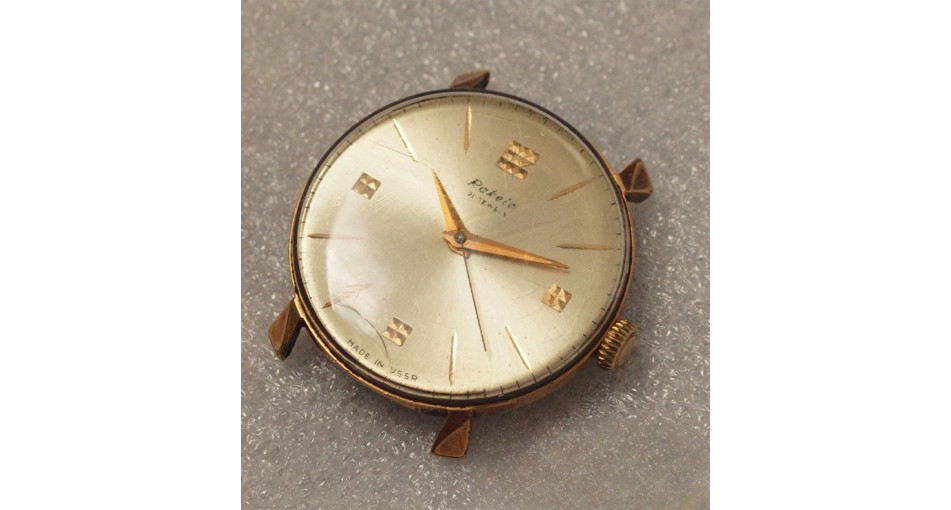
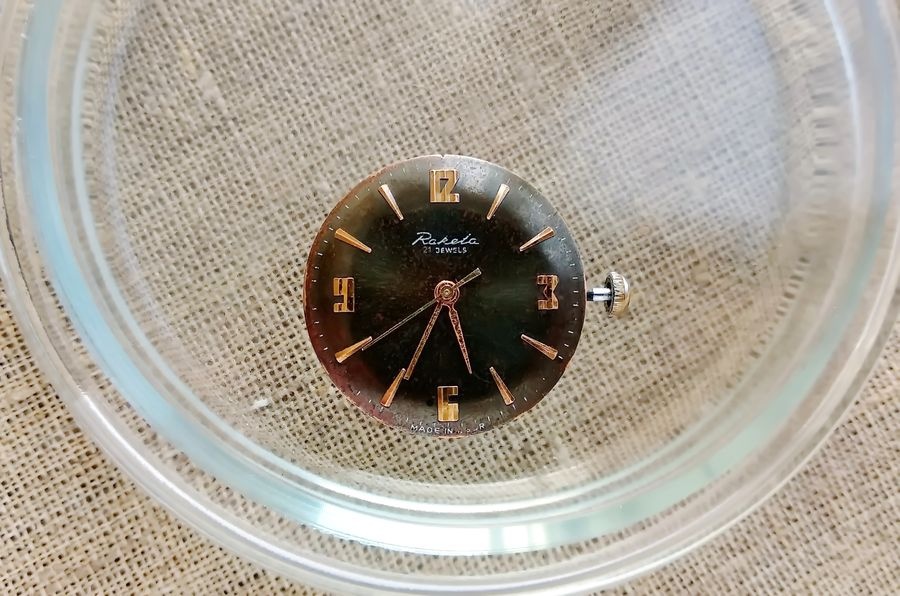
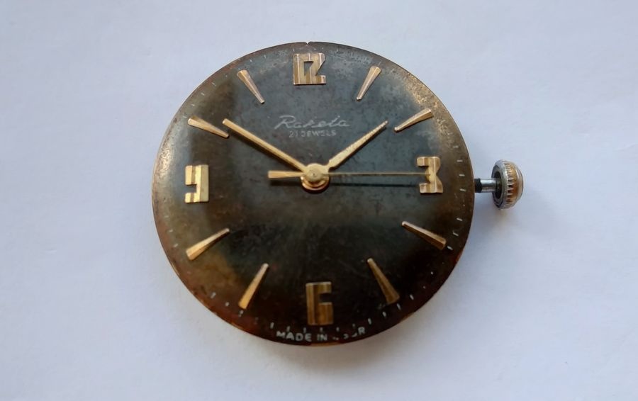
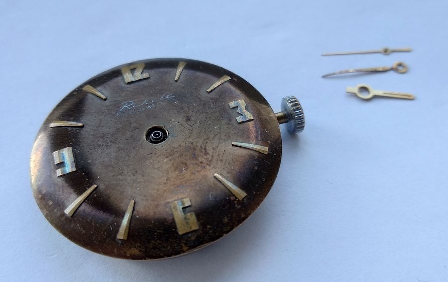
The watches produced on the 2609B received dials that remain attractive today. A careful polish of the printed characters, a light application of lacquer, and appropriate replacement hands would produce a presentable result with minimal intervention.
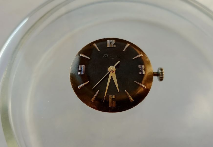
Original dials from the Baltika production period. The design holds its character after decades; the typography and index arrangement reflect mid-century Soviet practice without the decorative excess that characterized some contemporary export pieces.
Disassembly
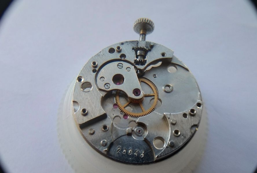
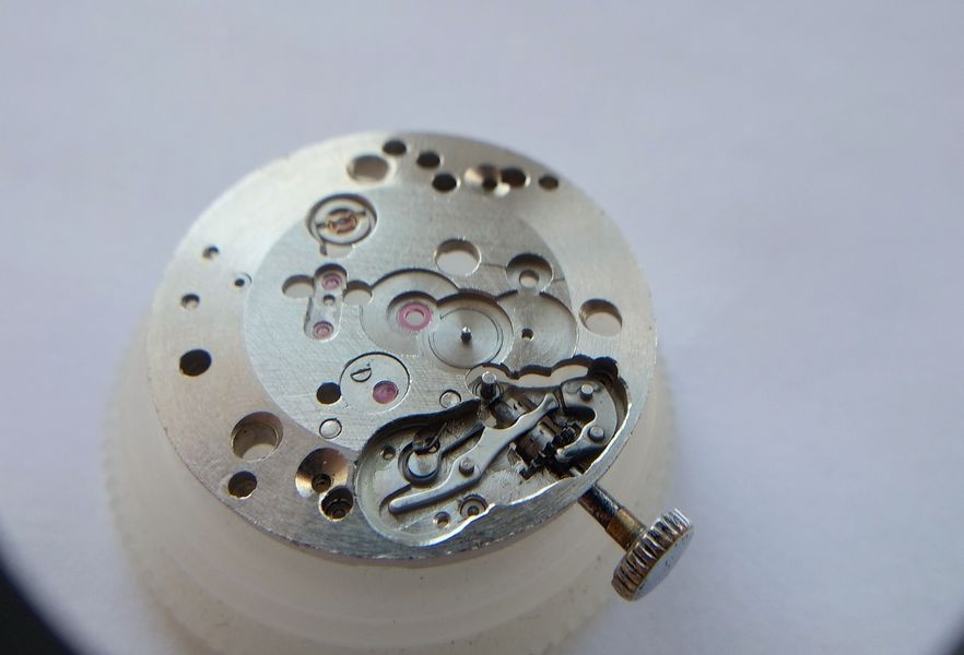
The specimen under examination is a Raketa Baltika carrying caliber 2609B. Before disassembly begins, the movement is observed from both sides to note the condition of the major components and identify any pre-existing damage.
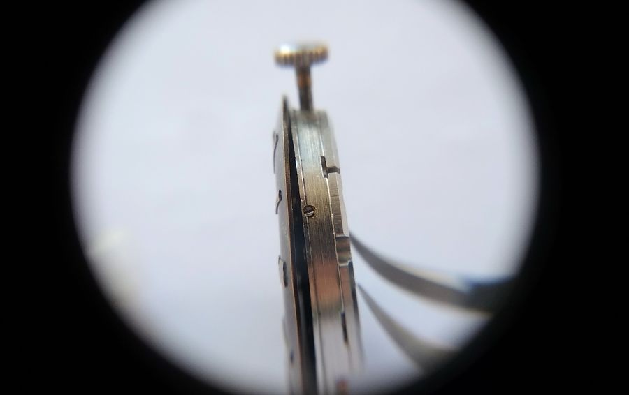
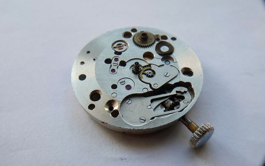
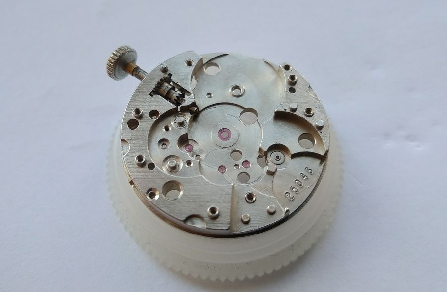
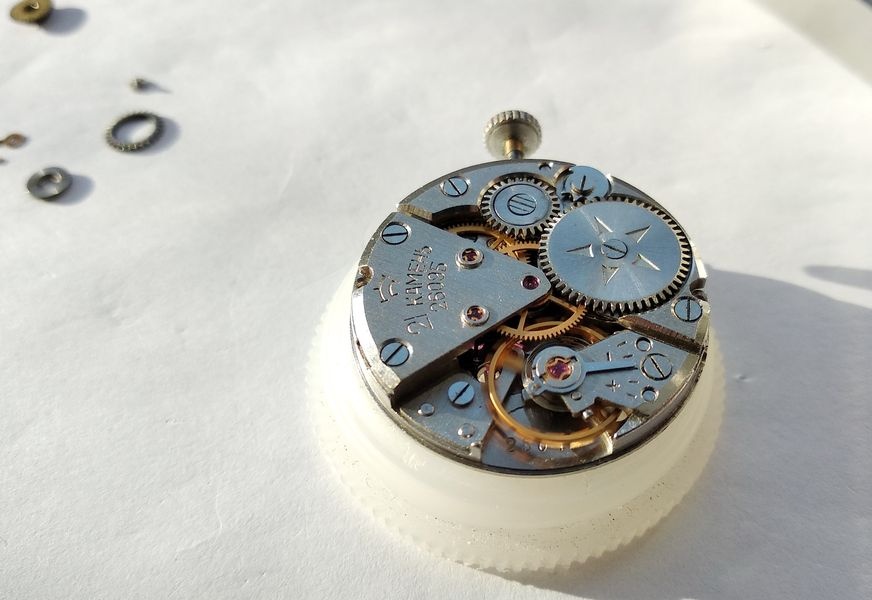
From the dial side, the strongly domed profile of the Baltika case and dial is immediately apparent. The main plate carries deep bevels around its perimeter — a structural consequence of fitting the movement into a domed case — that, as will become clear, precluded any calendar complication in this caliber family.From the movement side, the gear train bridge draws immediate attention. Its sector profile and cantilevered mounting — secured to the main plate along one edge only — distinguish the 2609B clearly from the later 2609.NA, which introduced full-span bridges for both the gear train and center wheel. The cantilevered design is adequate for a manual-wind three-hand movement; it offers no accommodation for an automatic rotor.
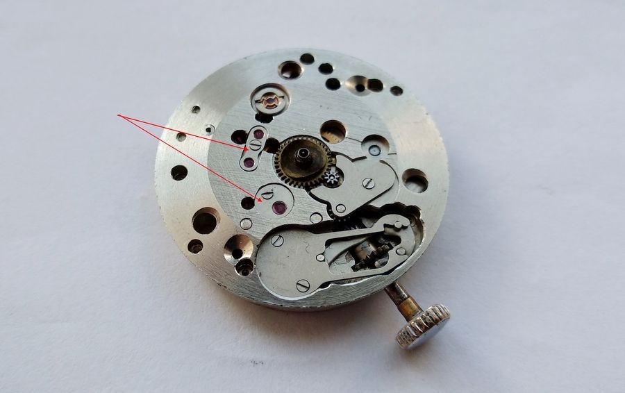
Hands and Dial
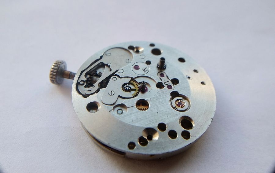
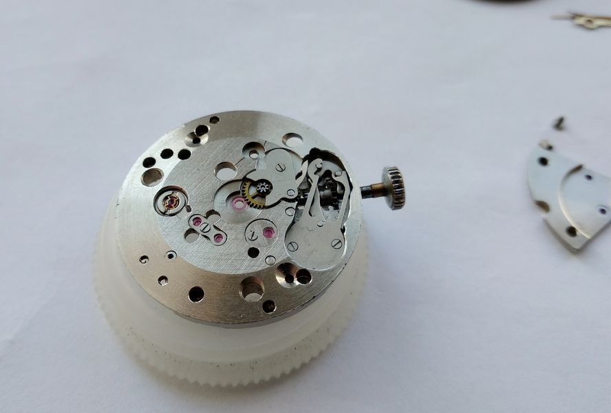
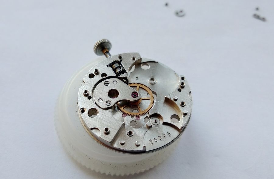
Hands removed without damage to the dial surface. The cannon pinion and center seconds pipe are exposed at the plate. Dial condition is assessed before the dial-securing screws are touched — a dial worth preserving should be handled with appropriate care at this stage.With the securing screws released and the dial lifted free, the under-dial side of the movement is exposed. Several features visible here merit closer examination before disassembly proceeds further.The under-dial view reveals two significant engineering characteristics. First, the main plate perimeter carries pronounced bevels — a consequence of the domed case architecture, and the reason no calendar disc can be fitted under this movement. Second, and more consequential for the service procedure, virtually every gear train pivot position is covered by an overlay cap jewel. The sole exception is the seconds wheel. This near-complete coverage with oil-retaining jewels is a deliberate engineering commitment that distinguishes the 2609B from the base 2603 and explains much of the caliber's service longevity.
Under-Dial Train
The hour wheel lifts free without resistance. Its orientation is noted. The cannon pinion is the next component to be addressed.The cannon pinion sits at friction on the center wheel arbor. The friction coupling must be overcome with controlled, axial force — sufficient to free the pinion without displacing the center wheel laterally in its jewel. A dedicated cannon pinion tool is the correct instrument; improvised methods risk pivot damage or jewel fracture.
Balance and Escapement
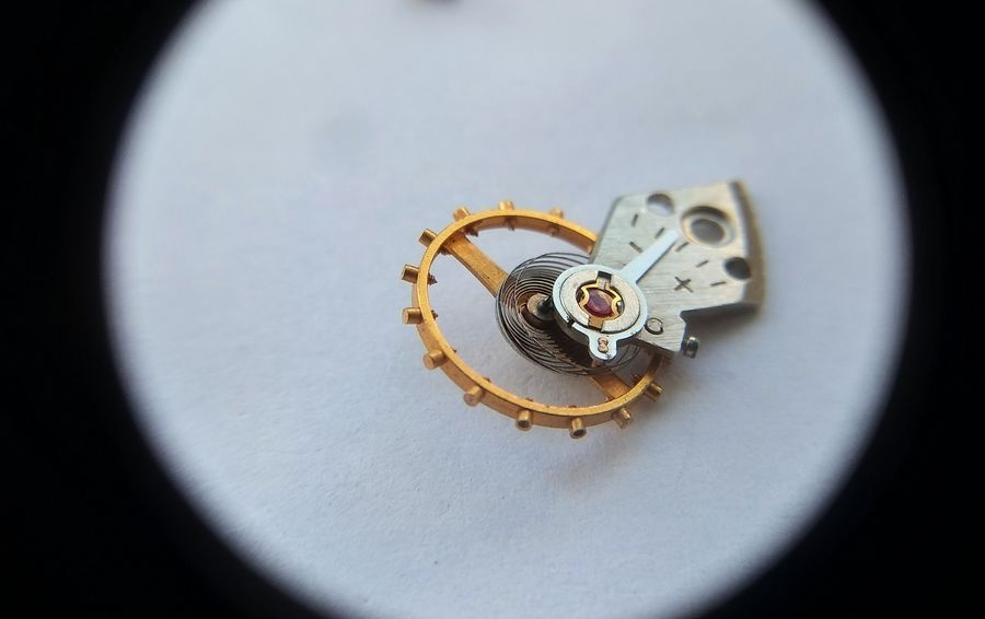
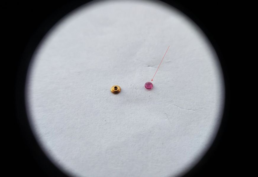
Balance assembly removed. The balance carries a screwed brass timing mass — original to the 2609B configuration — with a Breguet overcoil hairspring. Regulator pins engage the hairspring without a locking collet; the pin column is fixed. Anti-shock protection at both staff pivots is provided by Incabloc bouchons. The bouchon service will be addressed at the close of reassembly.The pallet fork bridge is slender: a narrow cantilevered plate held by a single screw. The bridge is removed and the fork assembly extracted. The fork pivot holes and pallet stone geometry are noted before the fork is cleaned.Pallet fork removed and laid out. The pallet stones are examined for chips, rounding at the locking faces, and correct angular positioning. Any disturbance to the stones during cleaning would require bench verification of the escapement geometry before reassembly.
Winding Mechanism
The winding wheel train is approached with the barrel bridge still fitted. Crown wheel and ratchet wheel are the principal components here. Their removal requires a properly fitted screwdriver to avoid deforming the click spring or displacing the click from its post.Crown wheel and ratchet wheel removed. Both are cleaned and inspected: ratchet teeth for chipping or wear, the click interface for peening or rounding. No complications specific to this caliber at this stage.
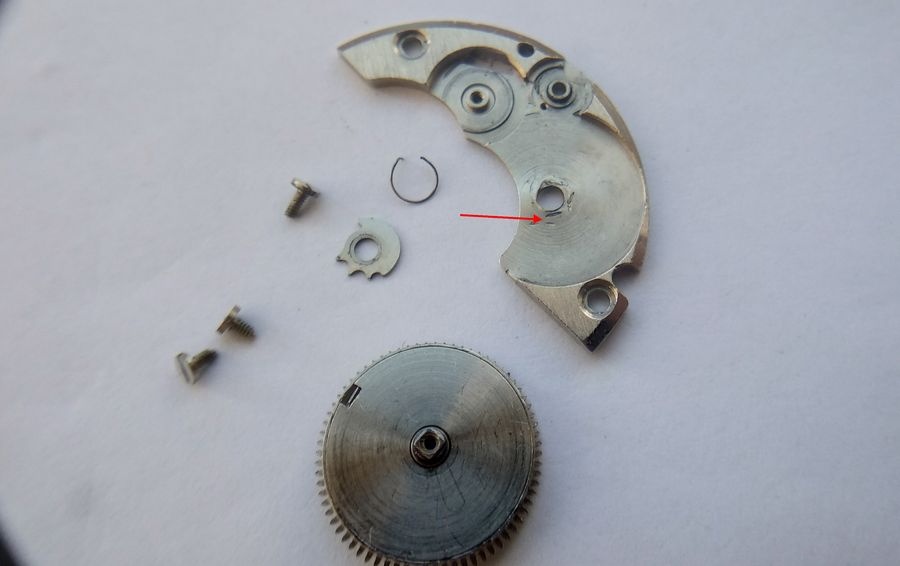
Barrel Bridge: The Characteristic Failure
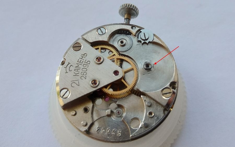
The barrel bridge presents the failure mode that afflicts this caliber family consistently — and indeed a number of contemporary Soviet movements of similar design. The pivot hole for the barrel arbor has worn oval from sustained metal-to-metal contact in the absence of adequate lubrication. In this specimen, a previous attempt to address the wear is visible: the oval aperture was compressed by peening, a stop-gap that rarely holds under continued service. A replacement bridge will be sourced and fitted during reassembly. The remedy in the 2609.NA was more considered: a hardened insert was pressed into the barrel bridge at this position, and a later variant — the 2610 — introduced a full jewel at the barrel arbor.The barrel bridge is retained by three screws — two short and one long. The long screw serves a dual function: it is also the post on which the mainspring click is mounted. This distinction must be carried through the reassembly sequence without error. Installing the click on a short post produces incorrect click geometry; placing the long screw in a standard bridge position wastes thread engagement and places the click incorrectly. These screws are not interchangeable.
Gear Train
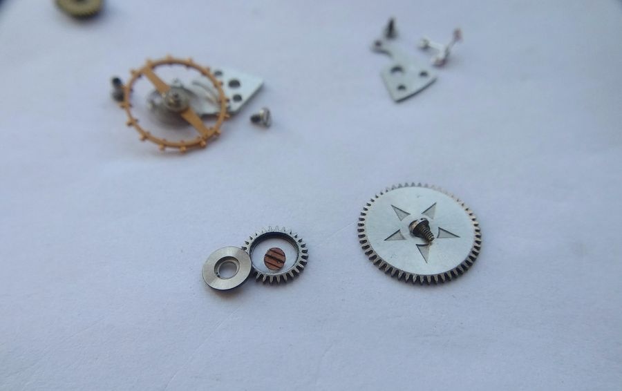
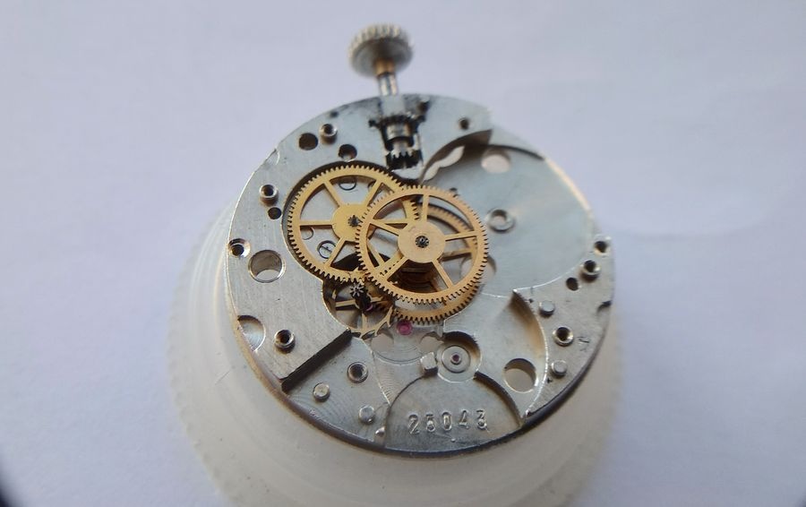
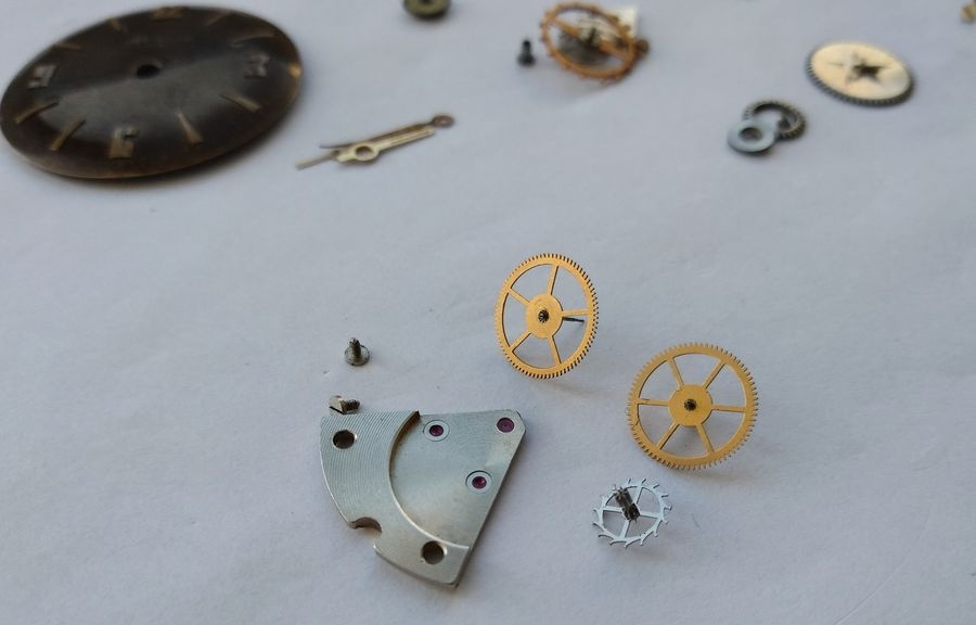
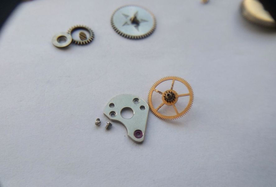
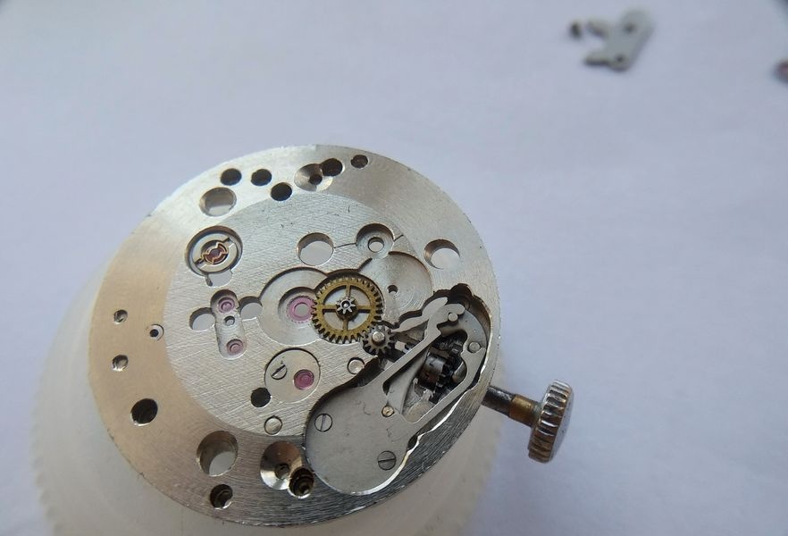
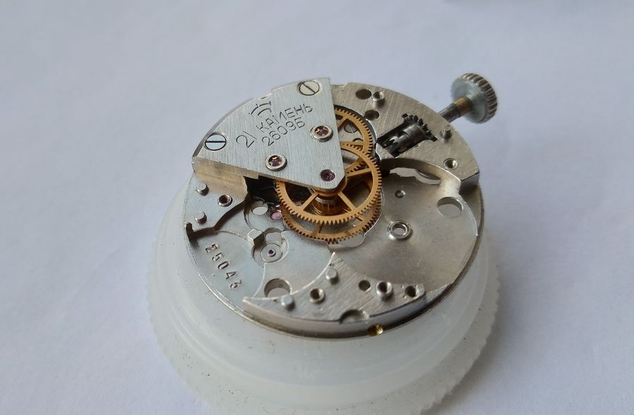
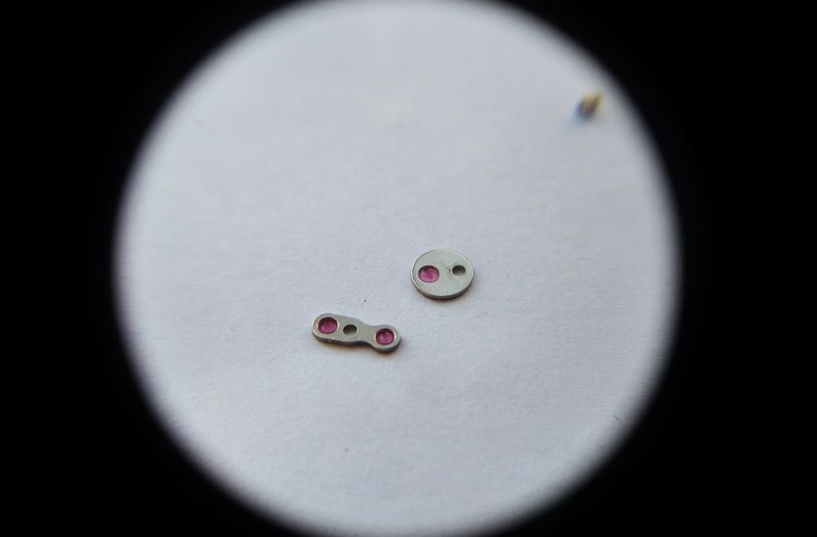
The gear train bridge is released and lifted. Its sector form was shaped around the Baltika case profile. The cantilevered mounting geometry — adequate for a manual-wind three-hand movement — left no possibility for attaching a self-winding module without a complete redesign of the bridge architecture.With the bridge removed, the full going train is visible in the main plate: seconds wheel, intermediate wheel, and escapement wheel, each seated in its jeweled pivot holes. The wheels are lifted in reverse order of their meshing sequence, each pivot examined for straightness and surface condition before cleaning.The gear train wheels beside the sector bridge. The overlay cap jewels are clearly visible on the bridge underside — small domed jewels positioned over the upper pivot holes of the escapement and intermediate wheels. Their purpose is oil retention, not shock absorption. The technical distinction has direct implications for how lubrication is applied at reassembly, and is discussed in full at the close of this documentation.The center wheel bridge is also cantilevered — mounted on one side of the plate only. In the 2609.NA, this component was redesigned as a full-span bridge crossing the plate, which improved positional rigidity and created a flat upper surface compatible with an automatic rotor mounting. In the 2609B, the cantilevered form is a consequence of the plate geometry and the case into which it fits.Center wheel removed. The arbor is checked for straightness and pivot condition. The jeweled center wheel bearing introduced with the 2603 — and retained through the 2609B — ensures that the upper pivot runs in a hard bearing rather than directly in the softer brass plate.
Keyless Works
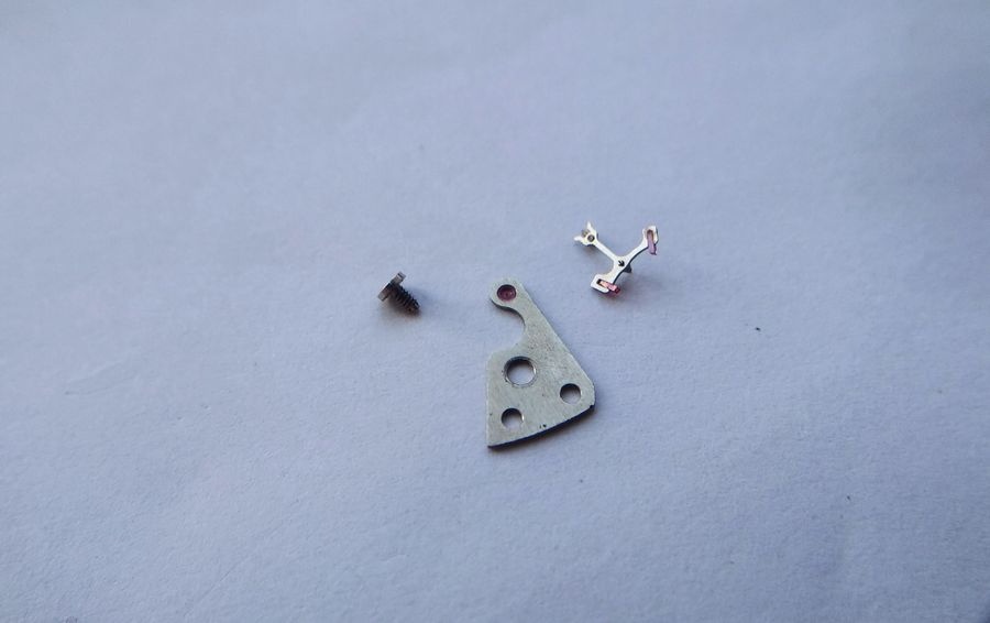
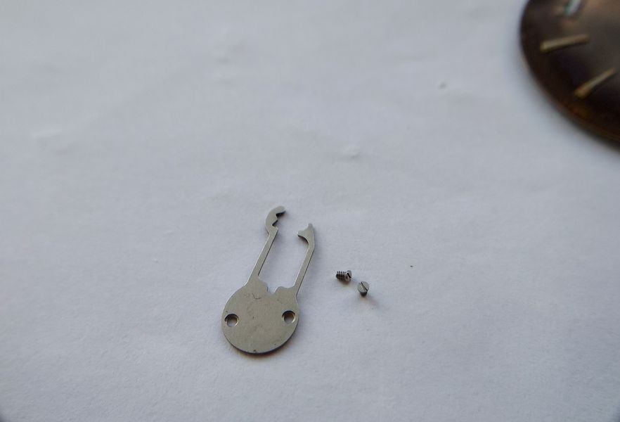
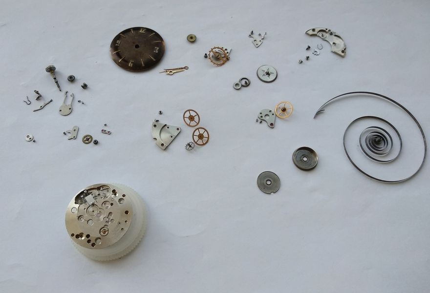
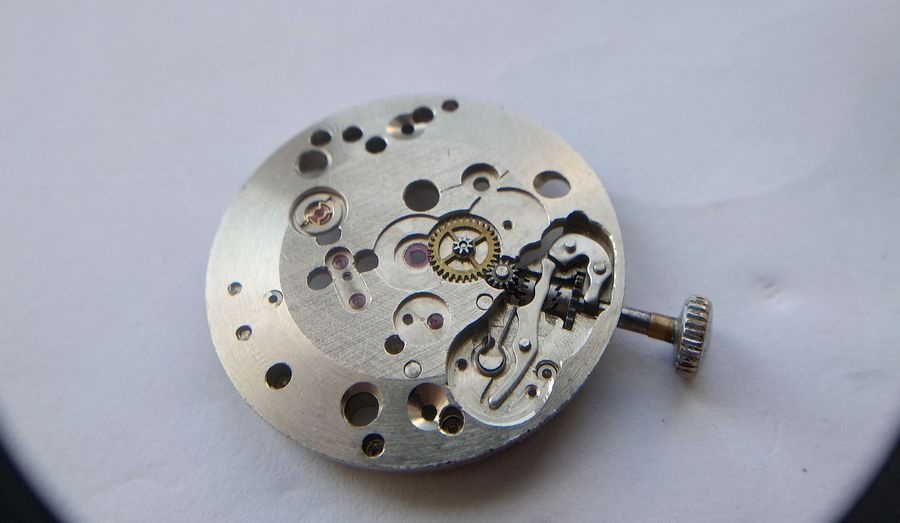
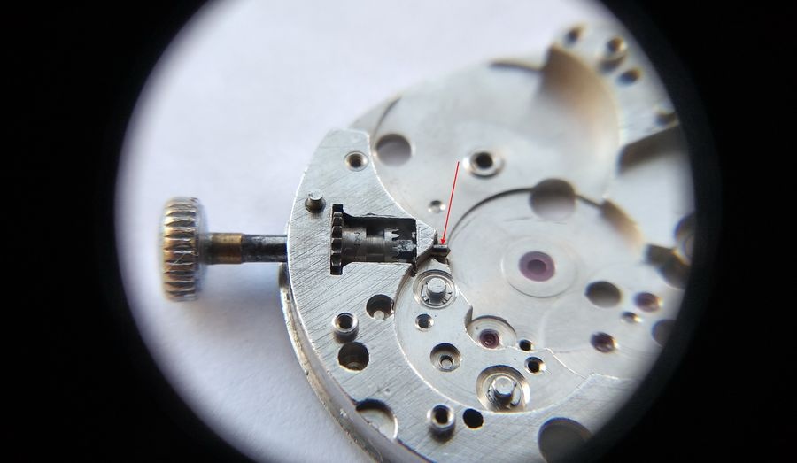
The movement is turned to the keyless works side. The setting lever, clutch lever, and yoke are visible in their assembled positions. The arrangement is simple — no complications specific to this zone — but the setting lever has one distinguishing feature noted at disassembly.The overlay jewels on the dial-side pivot positions are removed before the setting and clutch lever bridge is lifted. Removing overlay jewels without a supply of replacement retention springs in reserve is inadvisable — the springs are small, easily launched from the bench, and not universally available as a service part. The recommended alternative is to lubricate these jewels from the reverse face after soaking the bridge assembly in solvent, leaving the springs undisturbed.The spring cover for the keyless works is removed. Its profile is notably complex — a formed plate with multiple bends that retains the keyless springs in position while the stem is inserted and withdrawn. This same cover profile was carried forward unchanged into the 2609.NA: one of several points that indicate the later caliber was developed as a deliberate evolution of the 2609B rather than an independent design.The keyless works components are laid out. The setting lever carries a notably extended tail that functions as a geometric stop, limiting the lever's travel at the set position. This feature is particular to this caliber. The lever, clutch, yoke, and associated parts are cleaned individually and the sliding contact surfaces examined for wear.The setting lever spring is a simple straight leaf form. It functions adequately in service but lacks the refined geometry of the spring used in the later 2609.NA.The straight spring profile in context. The 2609.NA adopted an S-curved spring that delivers more consistent force through the full setting range. Both forms function; the revised geometry in the NA series reflects accumulated experience with the earlier design's limitations under repetitive use.Disassembly is complete. All components are separated and sorted on the work surface. The main plate, bridges, gear train wheels, barrel assembly, balance, and keyless works components are individually identified before the cleaning stage.
Reassembly
After cleaning in watchmaker's solvent and thorough drying, reassembly proceeds in reverse order. The keyless works side is addressed first.
Keyless works reassembled. The setting lever, clutch lever, and yoke are installed and their range of movement verified before the bridge is lowered. Oil type Б-1 is applied to the sliding contact surfaces of the lever and clutch. The spring cover is then fitted and the stem introduced to confirm correct engagement through wind and set positions.The winding stem tail — the cylindrical section that bears against the plate and keyless works lever surfaces during normal winding — receives a measured application of oil. This surface is subject to continuous rotary friction during crown operation and must not be left dry.
Gear Train
The center wheel jewel in the main plate receives a precisely measured drop of Moebius 8000 gear train lubricant. Correct quantity governs performance: insufficient oil leads to rapid pivot wear; excess oil migrates along the arbor toward the cannon pinion mesh, increasing train friction and risking adhesion between gear teeth under temperature change.Center wheel installed. The pivot is seated in the jewel with no perceptible lateral displacement beyond the designed endshake. The cannon pinion arbor passes cleanly through the plate to the dial side.Center wheel bridge installed and screwed down. The upper jewel in the bridge is lubricated after the bridge is fully secured — oiling before tightening risks distributing the oil unevenly as the bridge flexes under the screw. Correct endshake of the center wheel is verified by gentle axial pressure: a slight but detectable float indicates the pivot is free in both jewels.Seconds, intermediate, and escapement wheels reinstalled in the plate. The sector bridge is lowered onto the pivot jewels — the escapement wheel required minor positional adjustment before the bridge seated cleanly; the remaining wheels dropped in without correction. All pivots are confirmed in their jewels before any bridge screw is tightened. Gear train function is verified by turning the barrel arbor: all wheels should rotate freely with no perceptible obstruction or intermittent drag.
Overlay Jewels and Cannon Pinion
Each overlay cap jewel receives a carefully measured oil drop before installation. The drop must be large enough to bridge the gap between the cap jewel and the through-jewel below it by adhesion when the jewel is seated, but not so large that it overflows the jewel perimeter and reaches the gear teeth. The relationship between oil quantity and retention geometry in overlay jewel configurations is addressed in the technical note at the close of this article.Overlay jewels seated and their retention springs engaged. The cannon pinion is then pressed onto the center wheel arbor with controlled force. The friction coupling must be firm enough to resist slippage during normal timekeeping — including the torque transmitted by the setting of the hands — but yielding enough to allow setting without stalling the center wheel against the gear train.
Mainspring Barrel and Barrel Bridge
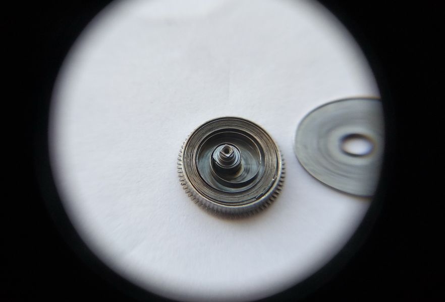
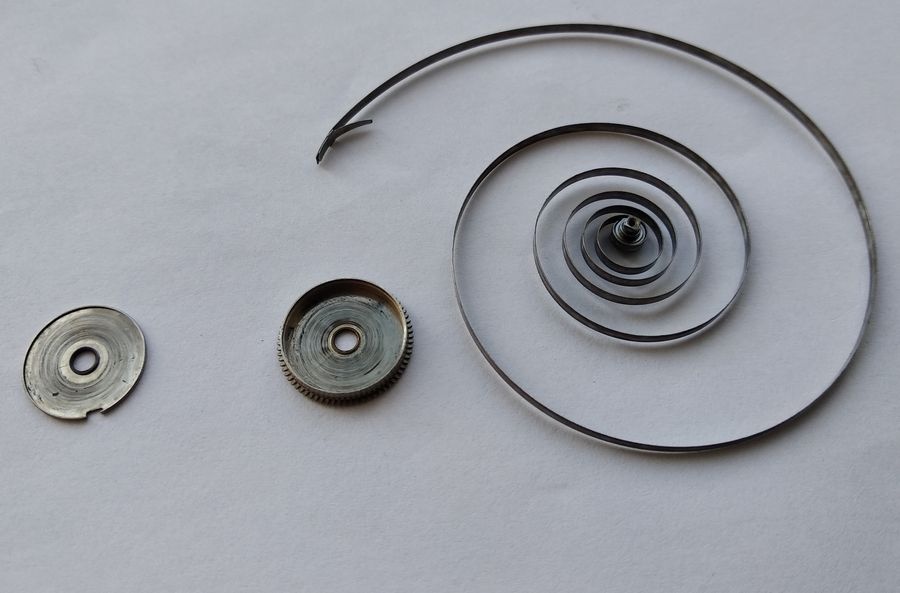
The mainspring barrel — washed, with the mainspring cleaned, dressed, and re-lubricated — is set into the main plate. The barrel arbor lower pivot seats in the jewel in the center wheel bridge. The mainspring should carry a partial pre-wind before installation to maintain even coil distribution against the barrel wall and avoid the mainspring lying fully flat.A serviceable replacement barrel bridge is installed in place of the worn original. The three mounting screws are placed according to their designated positions: two short screws at the standard bridge posts, and the long screw at the click post. The click is then positioned on the long screw post and the click spring engaged. Positive ratchet engagement is verified by manually winding the crown — the click should arrest the ratchet wheel cleanly with no slippage under reverse torque.
Pallet Fork and Balance
The pallet fork is installed with a precisely applied drop of Epilame-treated oil on each pallet stone face — impulse and locking surfaces. The fork pivot itself is intentionally left dry; lubricating the pivot introduces viscous drag into the escapement geometry and degrades the impulse efficiency. The balance is then lowered into position, the guard pin alignment checked, and the balance cock screwed down.
Bouchon Service
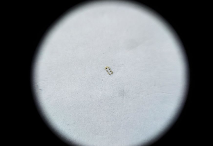
Bouchon service. The Incabloc unit is disassembled by soaking in watchmaker's solvent until the cap jewel's retention spring releases. The cap jewel, through-jewel, bouchon body, and lyre spring are cleaned separately, dried thoroughly, and then reassembled. Oil is applied to the assembled and installed bouchon in a final step — only after the balance is seated and stationary in its cock. The reason for this sequence is explained in the technical note below.The lyre spring that secures the bouchon in its seating groove. This component represents a persistent hazard in this caliber family — and in Soviet Raketa movements generally. The spring is not positively locked into the groove; it sits by friction only. Removal and reinsertion carry a genuine risk of the spring becoming airborne. On most workshop surfaces, a lost lyre spring is unrecoverable. Handle with appropriate attention.The movement is running. Balance amplitude is observed and the escapement rhythm audited before any rate correction is attempted. The gear train runs freely under mainspring torque; no intermittent drag is detectable. The escapement is even.Temporary test hands fitted to verify timekeeping under the load of hand mass. The case — awaited from a supplier — will determine the appropriate production hands for final assembly. Rate testing on the timing machine follows before casing.
Lubrication and the Function of Overlay Jewels
The closing technical note addresses a point that is commonly misunderstood even among experienced practitioners: the purpose of overlay cap jewels in the gear train is not shock protection. That function belongs exclusively to the Incabloc bouchon system at the balance staff. The overlay jewels in the gear train of the 2609B exist to manage oil retention, and a clear understanding of the distinction is essential for applying lubrication correctly during service.
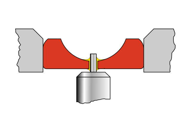
Schematic cross-section: a gear train pivot in a standard through-jewel. Oil occupies the annular clearance between the pivot shank and the jewel bore, retained by adhesive surface tension. The shoulder — the flat step at the base of the pivot shank where its diameter increases to the wheel body — acts as a mechanical barrier against downward oil migration along the arbor toward the pinion mesh. The oil quantity applied must be calibrated to fill the annular gap without bridging the shoulder: too little leaves the pivot under-lubricated; too much crosses the shoulder, flows to the pinion, and produces elevated viscous drag in the gear mesh.
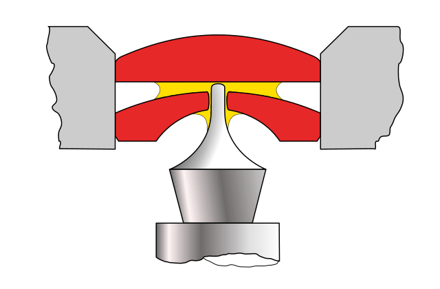
The balance staff presents a fundamentally different geometry. Unlike gear train pivots, the staff has no shoulder at the base of the pivot. The pivot tip is ground to a spherical profile — a deliberate choice that minimizes the contact area between the pivot and its jewel, allowing the balance to oscillate with minimum friction regardless of its orientation in space. The absence of a shoulder removes the only mechanical barrier against downward oil migration. Under gravity and capillary action, oil applied directly to the staff pivot in a conventional through-jewel arrangement would migrate rapidly down the staff, entering the hairspring coils and contaminating adjacent surfaces.
This is precisely the problem the bouchon solves. Within an Incabloc unit, the through-jewel and the overlay cap jewel are held in close, controlled proximity by the bouchon body and its retention spring. Oil is held in the narrow gap between the two jewel faces by adhesion — the same principle that operates in the gear train through-jewel, but applied to a closed capillary space between two parallel surfaces rather than between a pivot and a bore wall. Because the oil is immobilized between two faces, it is effectively arrested against the forces that would otherwise drive it to migrate. This arrangement also significantly reduces evaporation compared to oil held in an open bore.
The critical implication for assembly procedure is this: if the balance is removed after the bouchons have been oiled, a portion of the oil will leave with the staff pivot, dispersing along the staff and rendering the bouchon under-lubricated. The bouchons must therefore be oiled as the final step in the assembly sequence — after the balance is permanently seated and the cock tightened. Any subsequent removal of the balance for any reason requires re-servicing the bouchons before reinstallation.
Schematic cross-section: the balance staff pivot in an assembled Incabloc bouchon. The spherical pivot tip contacts the overlay cap jewel at minimal area. Oil is retained between the cap jewel and through-jewel faces in the narrow capillary gap, immobilized by adhesion from both surfaces simultaneously. No pivot shoulder is present to arrest downward migration; the bouchon architecture substitutes a capillary gap for the mechanical barrier. The same adhesive retention principle governs the overlay jewels in the gear train bridge, though the geometry there involves a shoulder-bearing pivot rather than a spherical tip.
With this understood, the engineering rationale of the 2609B becomes clearer. The near-complete overlay jewel coverage of the gear train pivots — every position except the seconds wheel — is not decorative, not a jewel count specification that existed to compete on paper with Swiss movements of the era, and not a shock protection system. It is a systematic approach to oil retention that extends the lubrication interval and reduces the rate at which the movement's performance degrades between services. The same logic was carried forward and refined in the 2609.NA. The earlier caliber — with its cantilevered bridges, its fixed regulator column, its straight keyless spring, and its vulnerable barrel bridge — was superseded for practical reasons. But its lubrication architecture was correct, and its successor inherited it intact.
Raketa Caliber 2609B: 21-Jewel Precursor to the 2609.NA
Raketa Caliber 2609B: Twenty-One Jewels and the Road to the 2609.NA