Cart
Your shopping cart is empty!
It's never too late to make things right :)
A complete restoration guide for the Industar-26m lens, from teardown to final assembly.
In some parts of the world, it is customary to throw out old things before the New Year and replace them with something new. That might make sense to some, but here in Europe—and among vintage camera enthusiasts worldwide—words like "vintage", "classic", and "collector's item" still command respect.
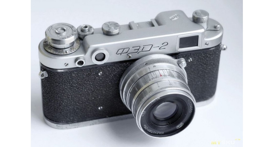
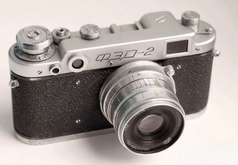
Right before Christmas, I got my hands on a well-used Industar-26m "P" lens from a FED-2 rangefinder camera. Although the FED-2 itself has largely faded into history, this particular lens model still has a loyal following. However, to use it effectively, a full overhaul was necessary. So, dear colleagues and fellow camera restorers, settle in—we're going to breathe new life into this piece of photographic history.
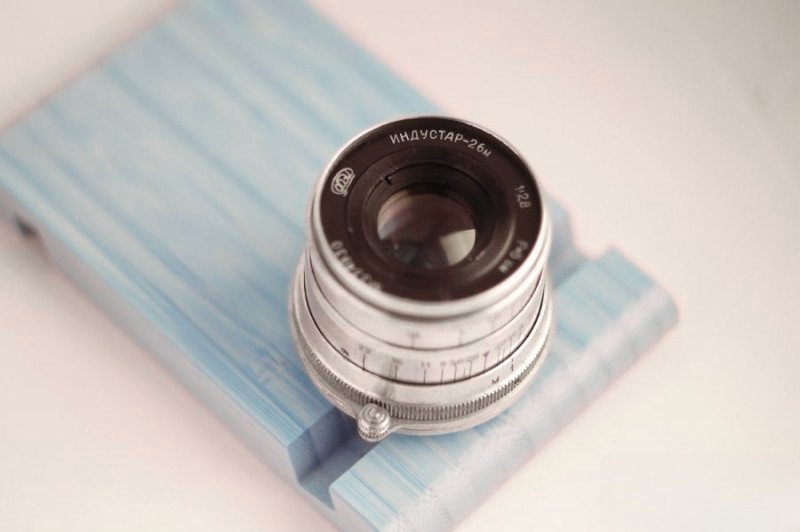
The Industar-26m is a fast, coated lens designed for rangefinder and early SLR cameras. It was mass-produced at the FED plant in Kharkiv, Ukraine, with a few small batches also made at KMZ. A version of it was even included with the Zorki-2 and the MIR camera.
There were experimental versions developed for single-lens reflex (SLR) cameras, as well as a dedicated enlarger variant known as the Industar-26m-U.
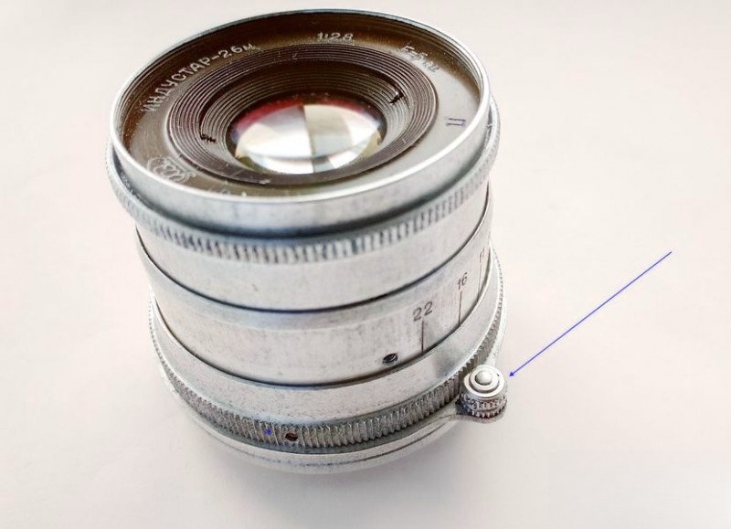
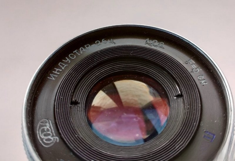
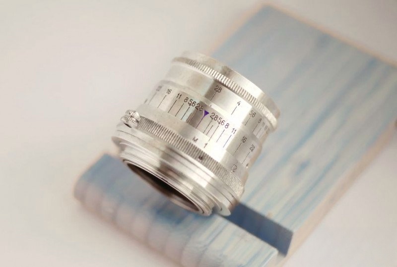
One of the standout features of early Industar lenses is the focus tab—a small protruding lever connected to the focusing ring. Though later models switched to knurled focusing rings, this tabbed design is something special. Why? Because the tab remains in a fixed position relative to the camera body, allowing experienced photographers to focus by touch alone. This is particularly useful in fast-paced situations, like street or reportage photography.
In fact, this grip style—sometimes called the "Leica grip"—lets you focus using the middle fingers of both hands while holding the camera with both hands simultaneously. It's intuitive and quick. For many photographers still loyal to rangefinder cameras, this design is more than nostalgic—it's practical.
So why was the tab discontinued? The argument was mechanical: the tab creates torque that may stress the helicoid threads, leading to premature wear. In theory. But the 70-year-old lens in front of me still turns like it should, so maybe the engineers overthought it. What's not working? The grease. But that's a different story.
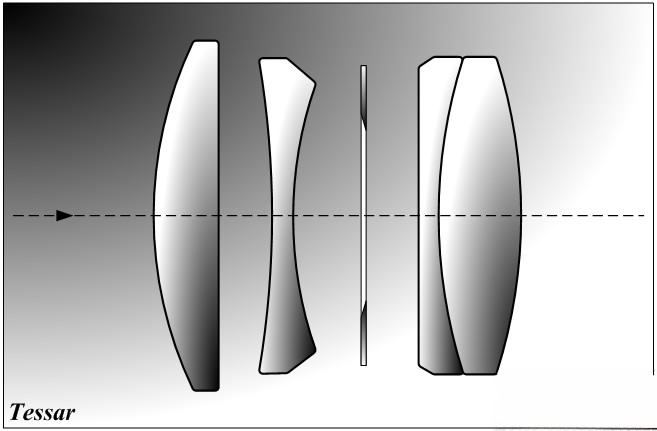
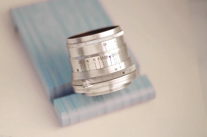
The lens in question is from a 1955 FED-2. The goal? Make focusing buttery smooth again, free the stuck aperture, and restore the finish without damaging the engravings or the optical coatings. This lens is especially appreciated for its 10-blade aperture, which creates near-circular bokeh—a quality it inherits from its optical ancestor, the Tessar.
Here's what we're working with:
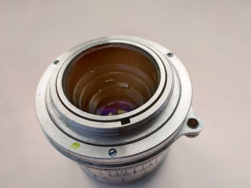
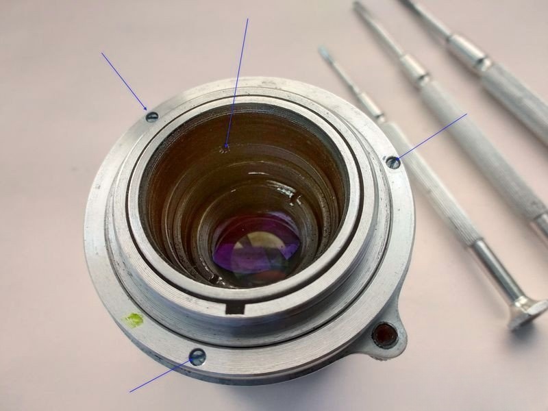
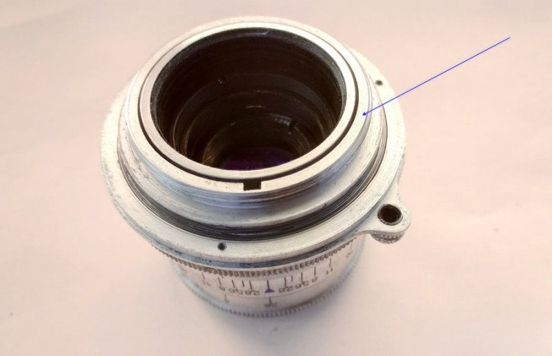
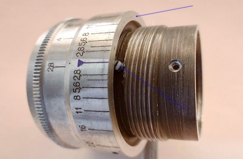
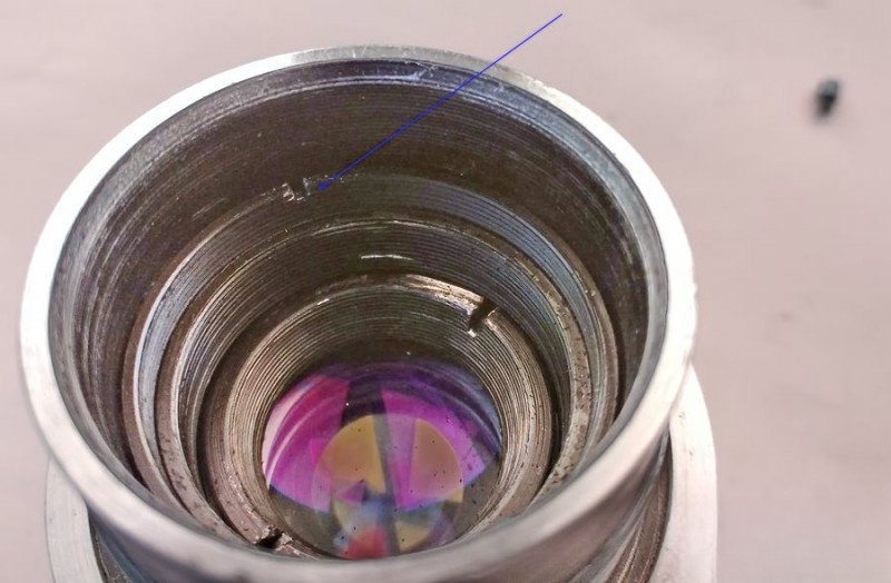
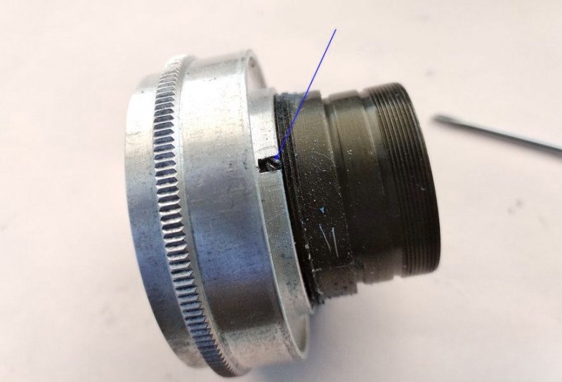
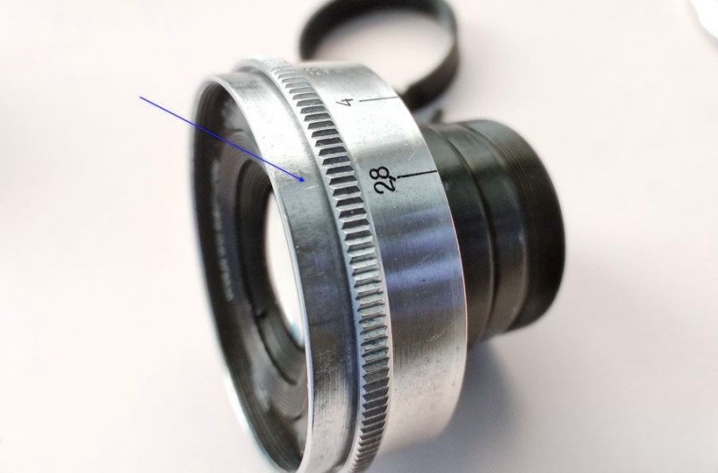
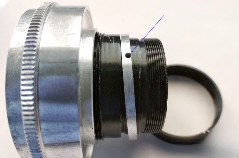
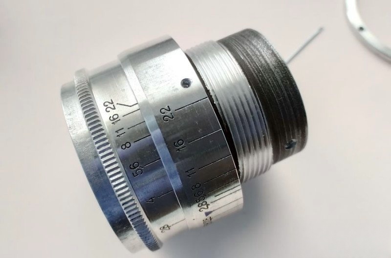
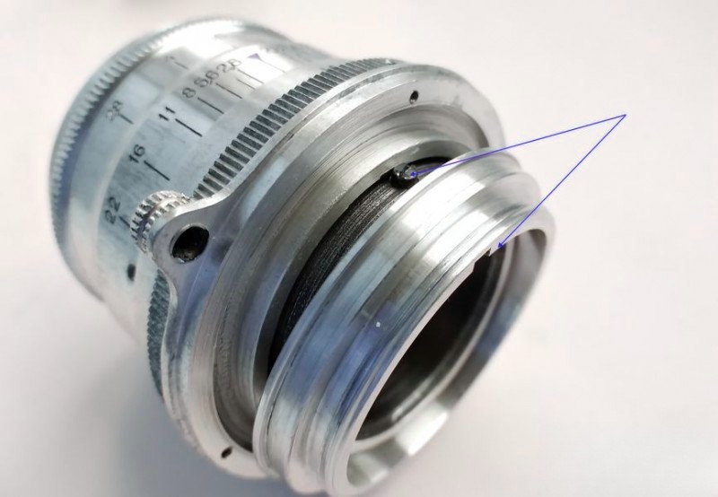
To begin the overhaul, we start by disassembling the helicoid. There are a few nuances here, so I'll walk you through each one carefully. The first step is to remove the three screws securing the guide ring of the rangefinder cam. I've also pointed out the retaining ring for the optical block—we'll return to it later.
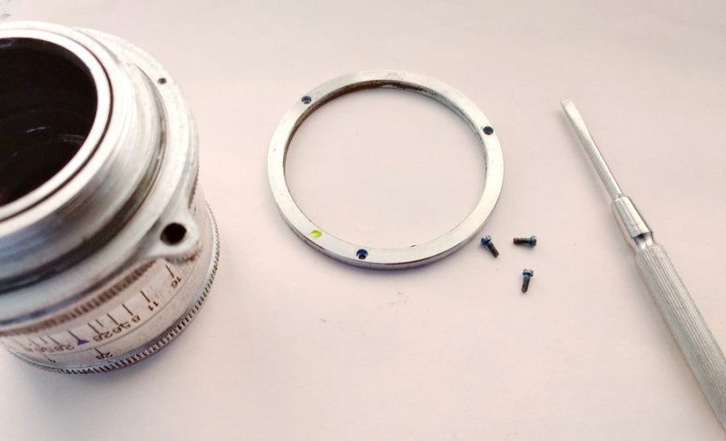
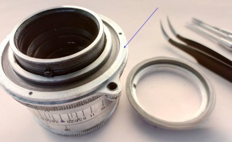
Once the screws are removed, the ring lifts off easily.
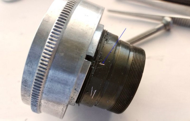
Next, remove the cam follower itself. It pulls straight up. This piece connects the lens to the camera's rangefinder system, transferring focus movement.
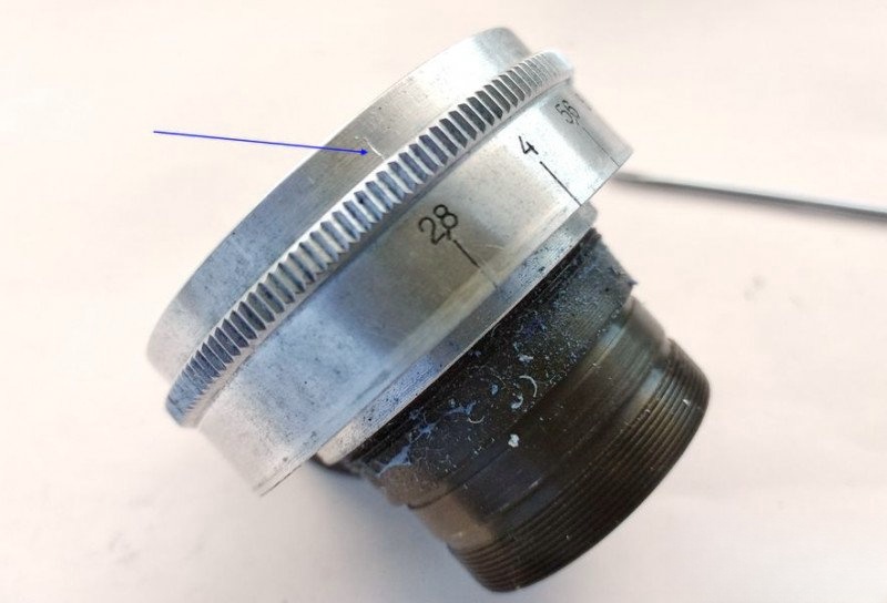
With that out of the way, it's time to unscrew the main focus ring—the part with the tab.
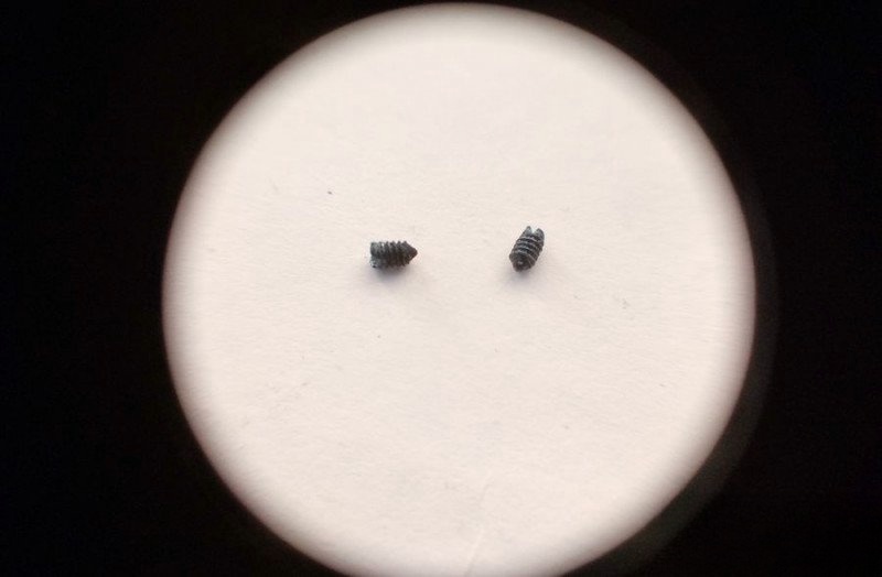
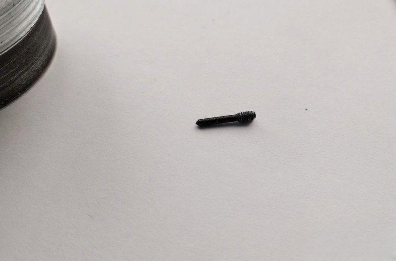
To do this, remove the single set screw that also acts as the rangefinder follower guide. It's multifunctional.
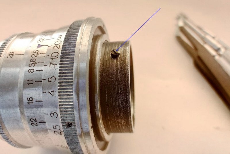
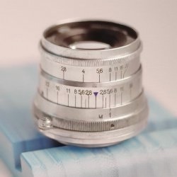
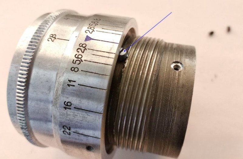
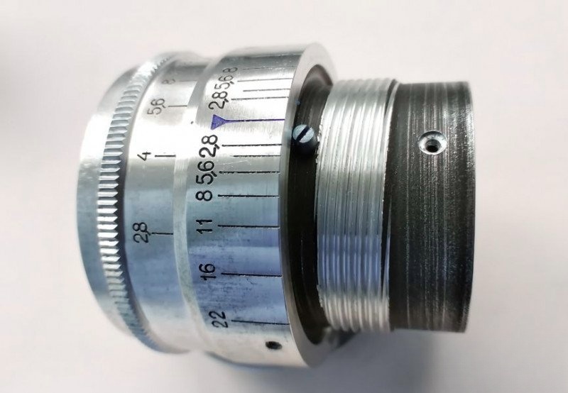
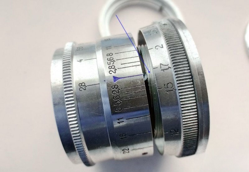
Carefully unscrew the ring while holding the depth-of-field scale in place. Stop when the 1.7m mark aligns with the red index line—this is where the threads disengage. Remember this alignment. Reassembly will be much easier if you do.
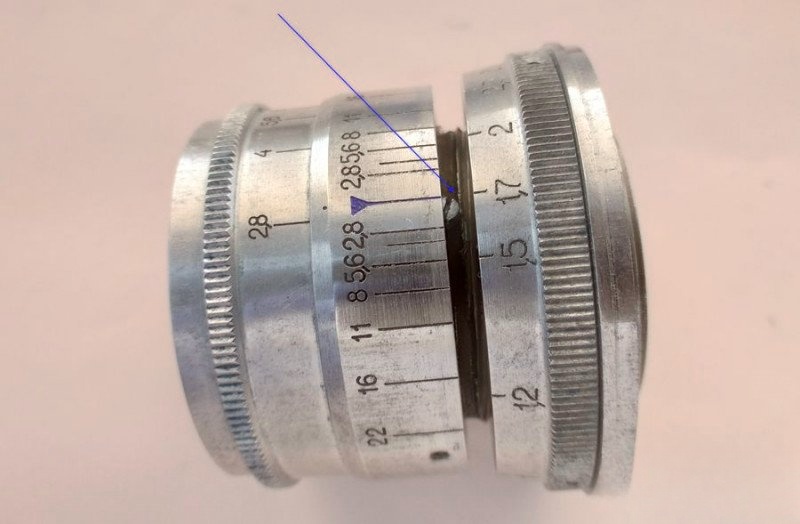
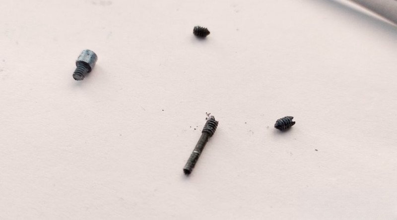
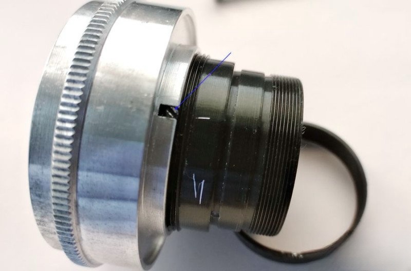
With the focusing unit disassembled, we turn our attention to the aperture, which is completely stuck. To fix this, we must remove the depth-of-field scale ring by undoing its limiting screw and two shallow screws.
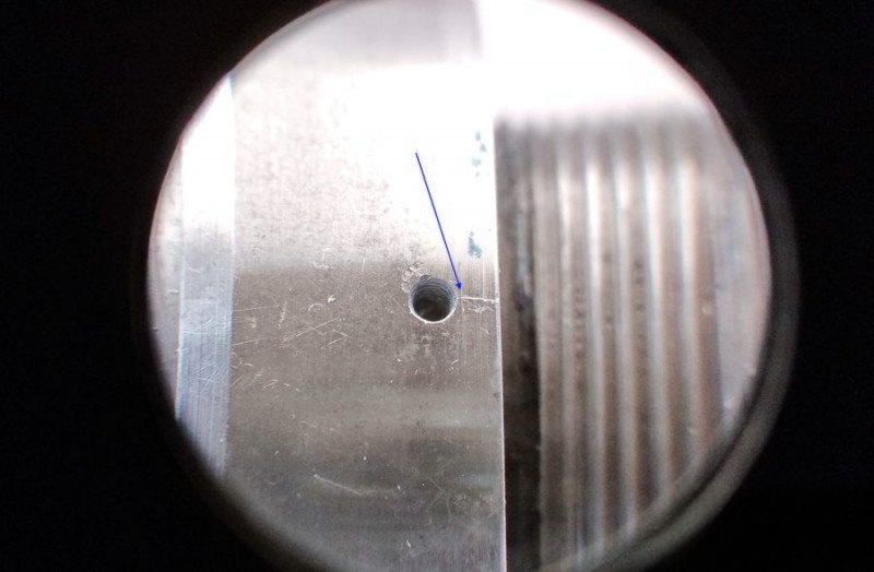
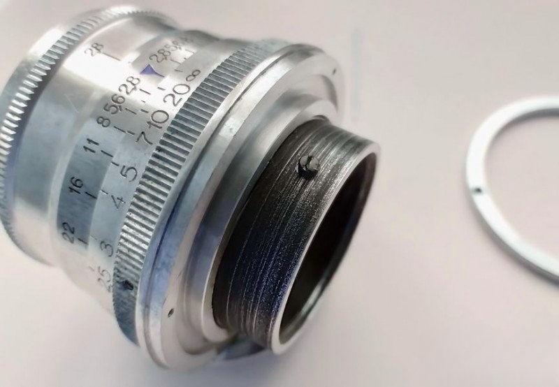
But pay attention—there's a third screw, seated much deeper. Mark its position but leave it for now.
Remove the two shallow screws first:
...and the limiter screw:
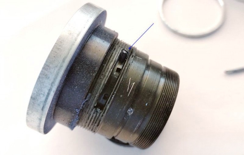
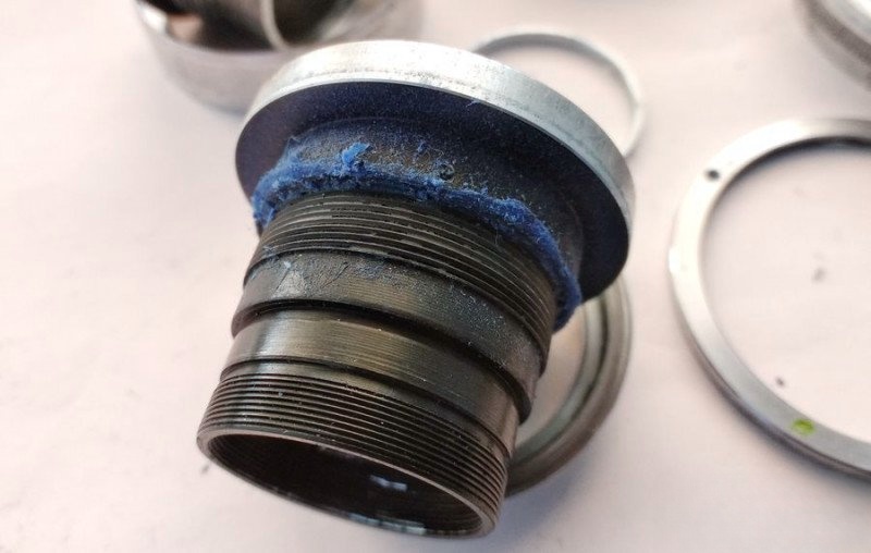
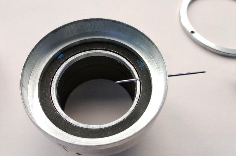
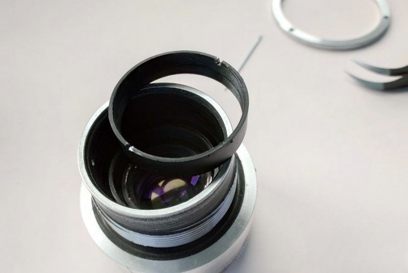
Now, use a lens spanner (or suitable substitute) to unscrew the internal retaining ring holding the optical block. We noted this earlier.
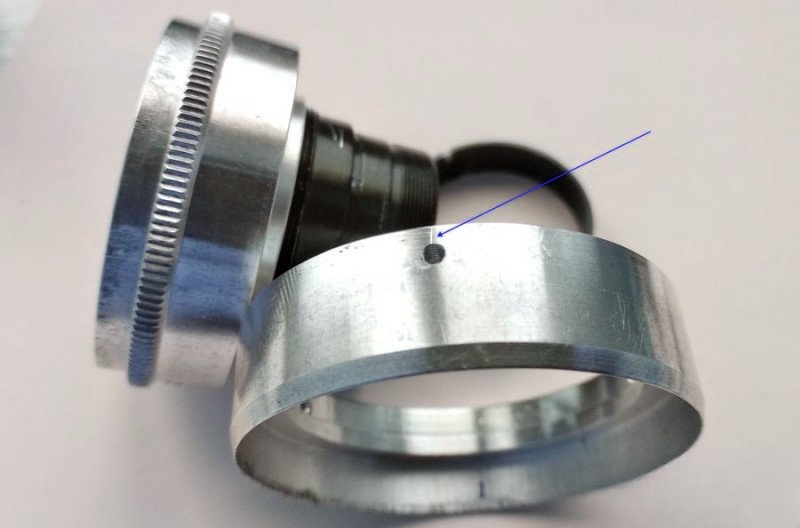
Now go back and remove the deep screw you marked before. This screw passes through the depth-of-field ring, the adjustment collar, and the helicoid barrel. It's long for a reason.
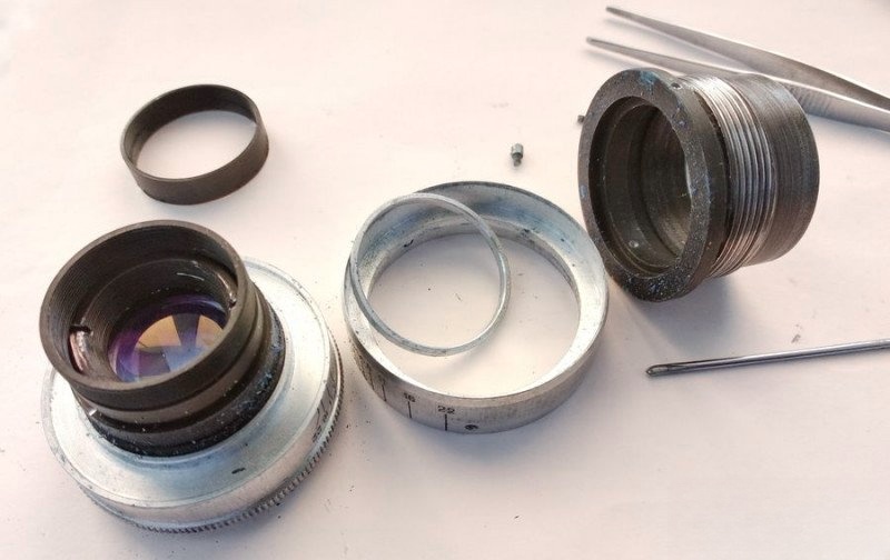
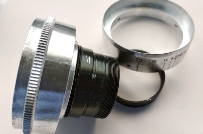
Once done, the optical unit is released. You'll now have the diaphragm control ring, calibration collar, and the rear helicoid barrel in hand.
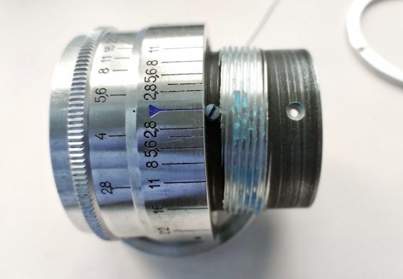
To proceed, open the aperture fully and mark the location aligned with f/2.8. This will help with alignment during reassembly.
Carefully remove the screw that connects the aperture ring to the diaphragm actuator inside. Don't force it—this part is delicate.
Make a reference mark beside the screw slot for proper orientation. Then, unscrew the diaphragm ring counter-clockwise...
...and immediately screw the removed screw back into the actuator arm to preserve diaphragm blade alignment. Precision here is critical.
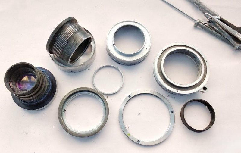
At this point, the lens is fully disassembled. All major mechanical components and threads are accessible.
Take a good look. Would you expect a diaphragm to work smoothly after 70 years of hardened grease?
Before final cleaning, I remove the worst grime manually with cloth and toothpicks.
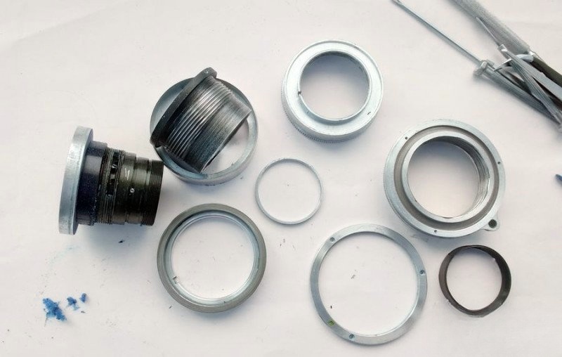
Then I soak the aluminum components in naptha overnight and clean them with borax to remove oxidation. Here's how they looked the next morning:
We begin reassembly with the diaphragm control unit. First, I apply a small amount of OKB-122-7 grease to the diaphragm ring threads, spreading it evenly across the thread. Be careful not to overdo it—excess grease can migrate onto the aperture blades.
Now I carefully unscrew the linkage screw from the actuator tab and begin threading the diaphragm ring clockwise until it seats fully. Then I back it off until the index mark aligns with our earlier reference line.
Check the alignment again. When the slot lines up correctly, reinstall the screw, making sure it bites into the correct hole on the actuator tab.
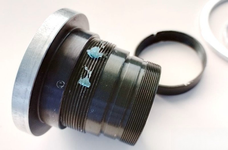
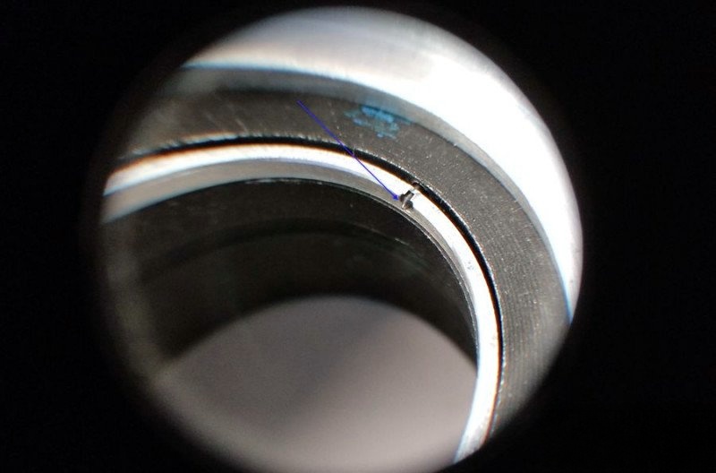
Take a close look at the lens block's rear—there's a recess designed to accept the tip of that long screw we removed earlier. We marked this area during disassembly.
Install the adjustment collar, lining up the hole to allow the long screw to pass through. Make sure the screw doesn't protrude too far—otherwise, the lens block won't seat properly into the helicoid barrel.
Now install the long screw carefully—just enough to hold the parts, but don't tighten it fully yet. We still need to eliminate any rotational play during final calibration.
Insert the entire optical assembly into the helicoid's rear barrel. Once seated, secure the short screws on the depth-of-field scale ring, but leave the long screw slightly loose for now.
Next, install the front retainer ring to hold the lens block firmly. This also allows you to center the optics and remove any play in the focusing system.
With the block aligned and stable, fully tighten the long screw and lock everything into position.
Apply fresh OKB-122-7 grease to the helicoid thread. Spread it thoroughly but sparingly along the working threads.
Now take the focusing ring with the tab and align it with the red index at exactly 1.7 meters, just like during disassembly. This ensures proper thread engagement.
Screw the ring onto the helicoid counter-clockwise until it stops, then secure it with the set screw in its original location.
Place the cam follower back in place...
...and tighten the three retaining screws. With this, the lens is fully reassembled and ready to go.
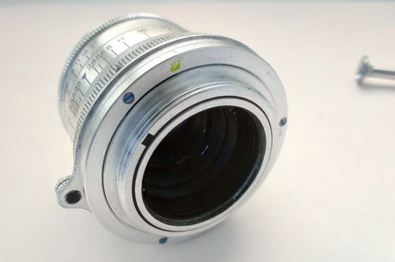
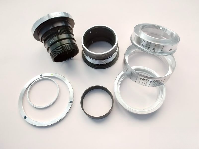
After full reassembly, the Industar-26m is finally ready. The aperture moves smoothly, the focusing ring glides with consistent resistance, and all external components are clean and intact. Here's how the lens looks now, fully restored:
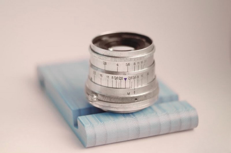
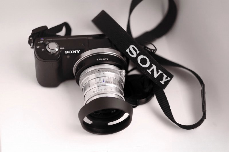
I also took the liberty of mounting the lens onto a freshly serviced FED-2 body. While this body might not see regular use, the lens definitely deserves a second life.
As for the optics—cleaning vintage glass is always a delicate affair. I use a time-tested method involving soot from a candle flame (carbon black) to gently lift oil and grime without scratching the coatings.
To showcase the lens's performance, I put together a whimsical test rig. Using a Sony A5000 mirrorless camera mounted on a tripod, I tested the freshly restored Industar-26m alongside two other Soviet-era lenses: the Industar-61 L/D and a 1955 KMZ Jupiter-8. Finally, I included Sony's native kit lens for comparison.
Each lens was tested under identical lighting, at the same focal length and aperture, shooting a ceramic figure I often use for lens comparisons.


As you can see, each lens offers its own character. The Industar-26m renders with pleasing contrast and vintage softness. The Industar-61 L/D is sharper at the center, while the Jupiter-8 introduces a creamier bokeh. The modern Sony lens, though clinically sharp, lacks the soulful rendering of its analog counterparts.