Cart
Your shopping cart is empty!
It's never too late to make things right :)
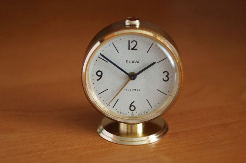
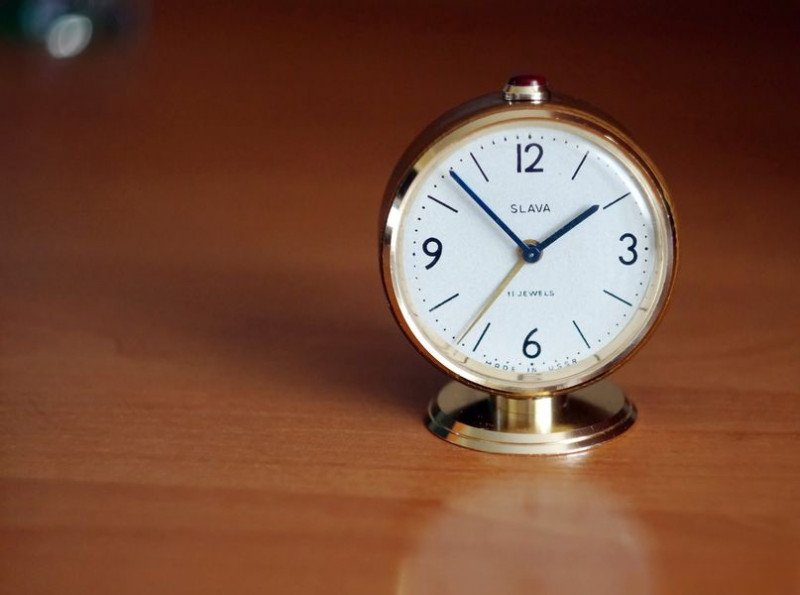
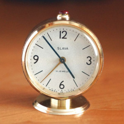
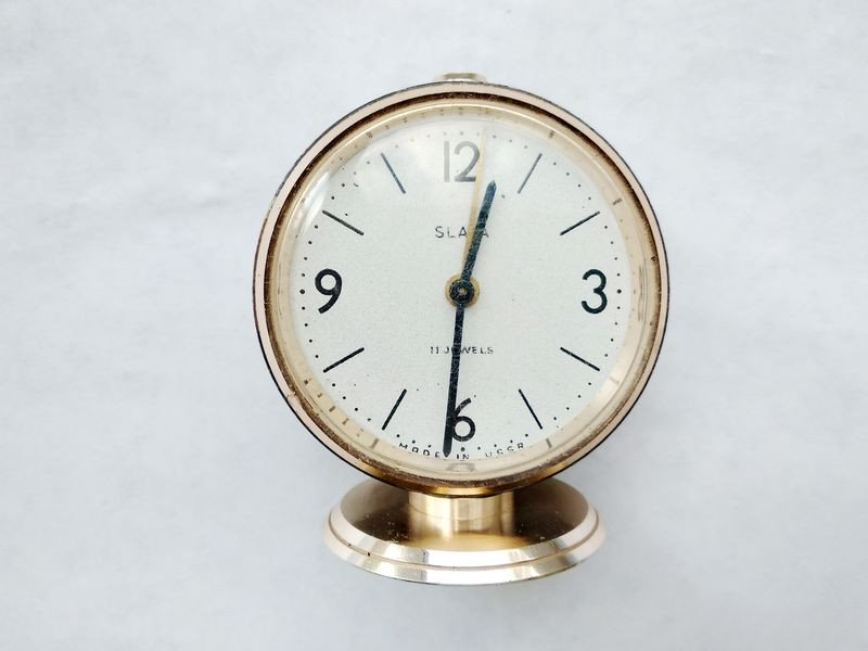
Recently, someone asked me why I haven't covered alarm clocks in my restoration projects. Well, today I have a perfect opportunity to dive into this fascinating timepiece niche. The Slava alarm clock is one of the most reliable and popular mechanical alarm clocks, though it belongs to a relatively high price category. Why? Because this clock features caliber 5671, built with eleven jewels - a rarity for alarm clocks. This particular Slava was renowned for its excellent performance, durability, and relatively high accuracy, especially when talking about early production mechanisms where no plastic parts were used. Today, we'll work with exactly this classic first version of caliber 5671.
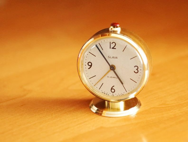
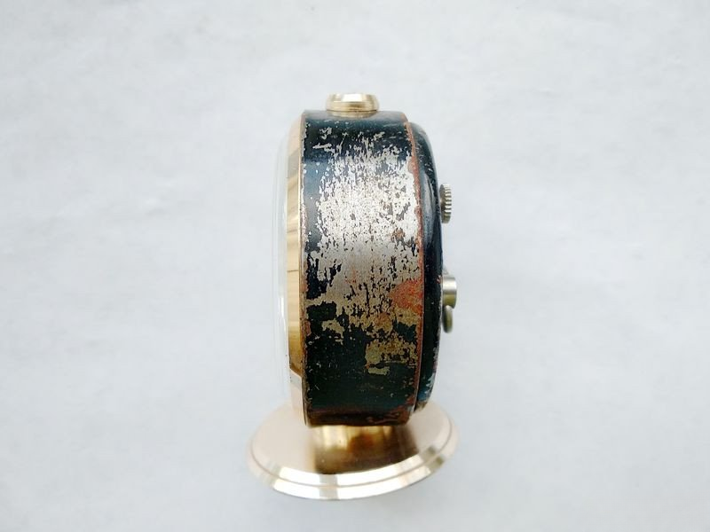
By fate's whim, this Slava alarm clock with mechanism 5671 from early production found its way to my workbench. It's an excellent mechanism featuring eleven jewels. Of course, working timepieces rarely make it to my workshop, and this one is no exception. Looking at this piece, I'm reminded of the old tale about the tar baby - it appears quite worn and weathered. I'll hide some of these initial condition photos under a spoiler to spare the sensitive souls of collectors.
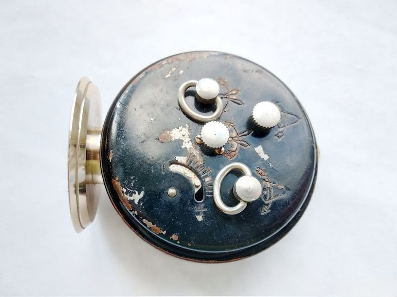
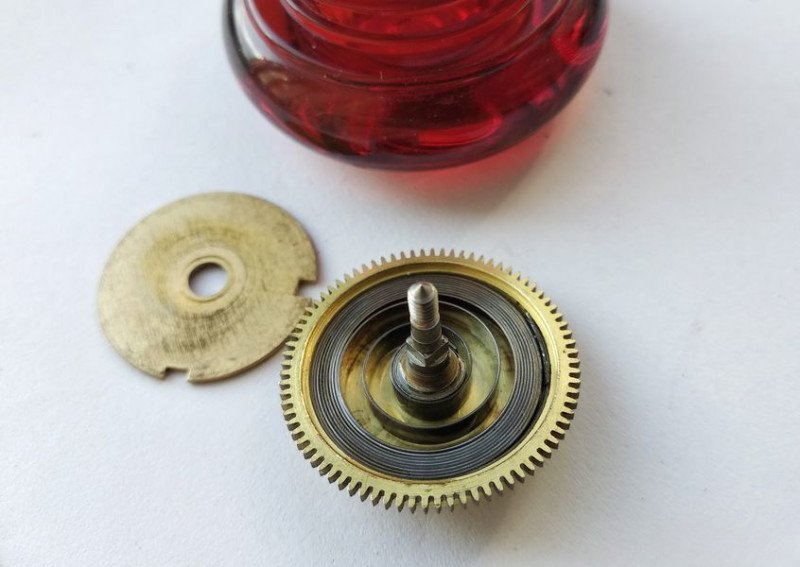
Well, we'll need to work on its appearance too. Let's begin our restoration journey. First, we'll remove the winding knobs for both the timekeeping and alarm springs. Interestingly, these springs differ in construction, as do their barrels. We'll see exactly how when we get to them.
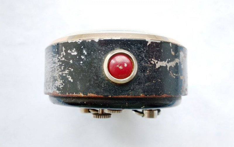
First, we need to unscrew the three screws securing the back cover, which also serves as the bell (or perhaps it's the other way around - not that it matters). This will give us access to the internal mechanism.
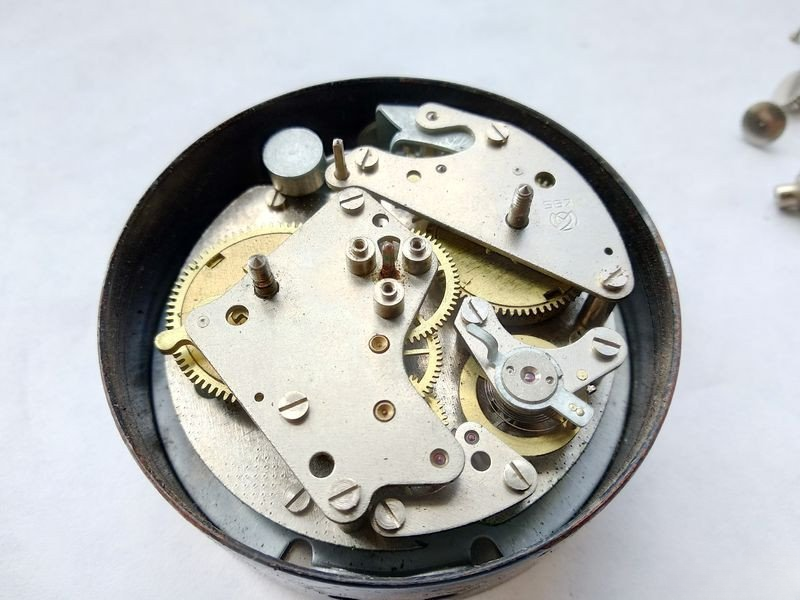
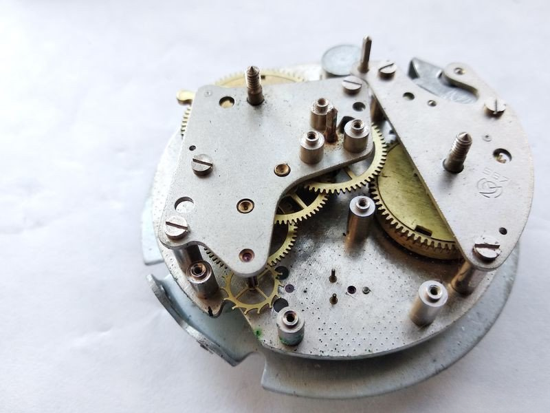
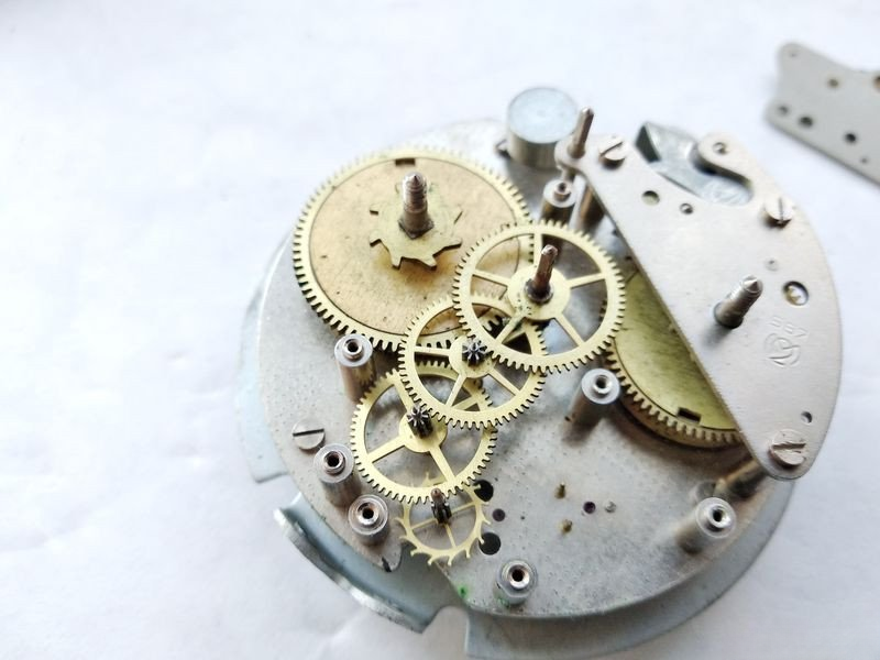
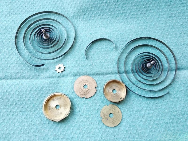
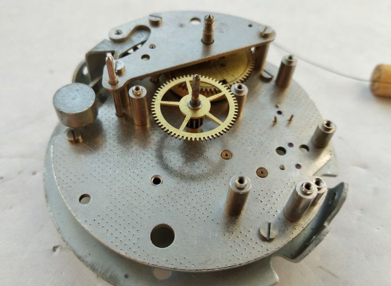
Now we can see the mechanism clearly. Immediately noticeable are both barrels - the timekeeping and alarm ones - made of brass. This is a significant advantage, as later "rationalization" would replace the alarm spring barrel with a plastic one.
Here we can see the Second Moscow Clock Factory stamp and the caliber type - 5671.
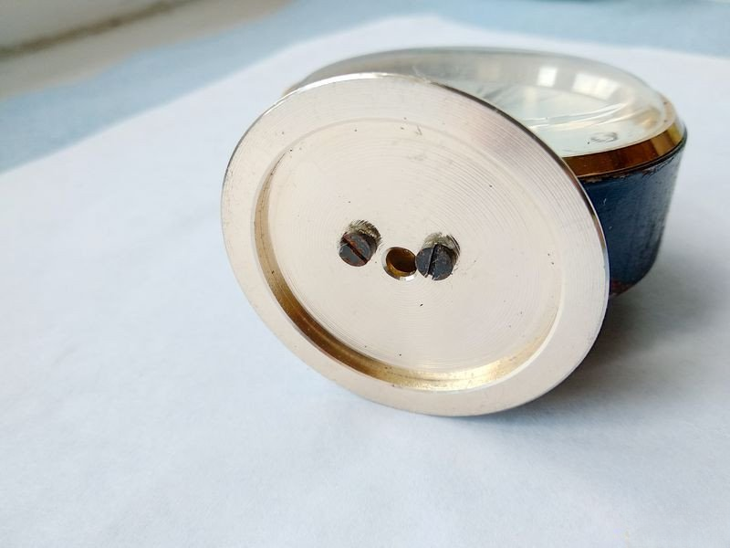
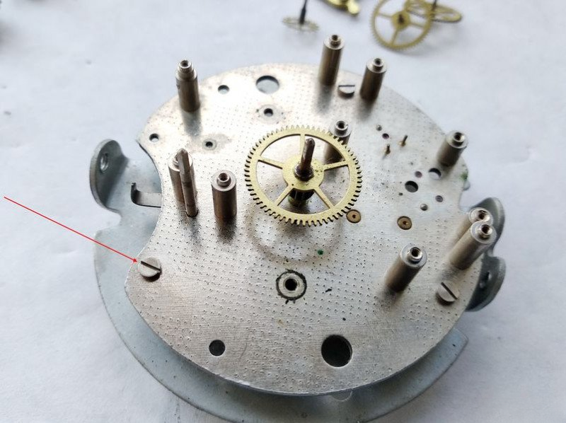
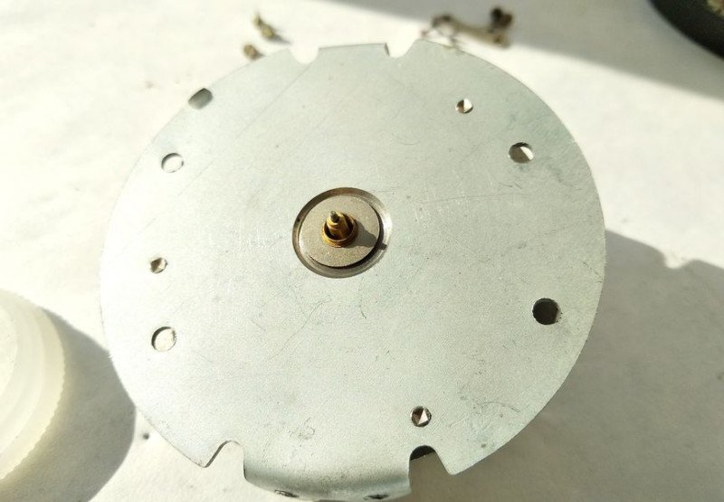
To remove the mechanism from the case, we first need to remove the stand. It consists of two parts and is secured by two screws that thread into the mechanism's plate bend.
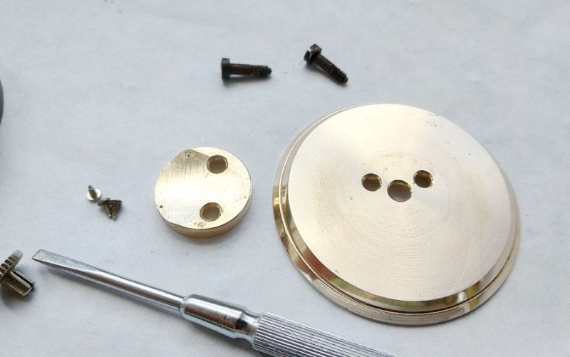
Here at the bottom, you can see the bend for mounting.
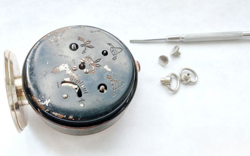
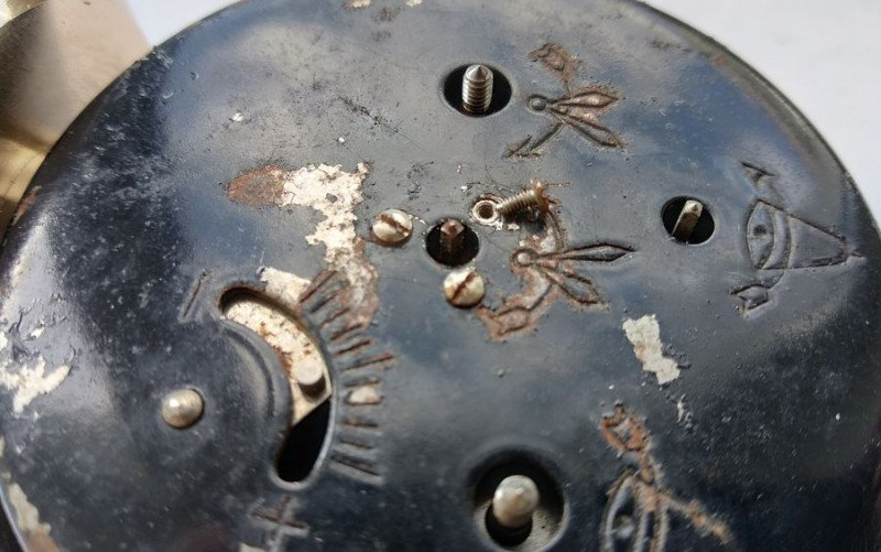
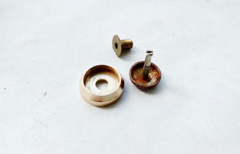
We've removed the stand, but there's still more to do. In the upper part, the mechanism is secured by a threaded bushing through which the alarm shutoff button's stem passes. Let's look at it more closely.
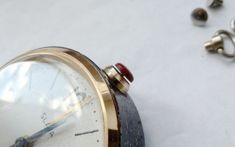
Here's how it looks inside. First, we need to extract the button itself from the bushing channel. We compress the spring prongs with tweezers and pull out the button.
Indeed, there's quite a bit to clean here...
Now we can unscrew the bushing itself using tweezers.
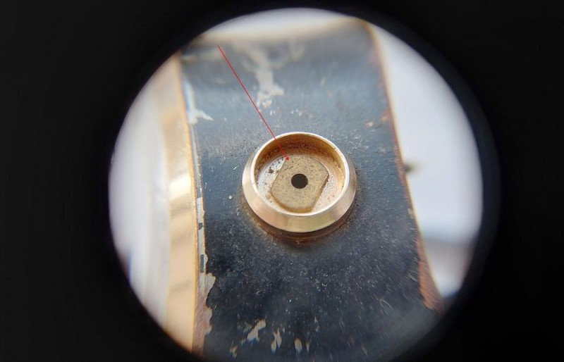
This "sandwich" comes out together with the decorative plate.
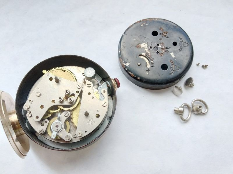
Now the mechanism can be freely removed from the case.
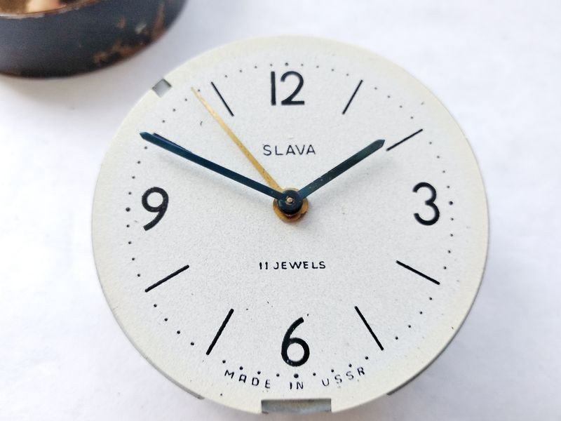
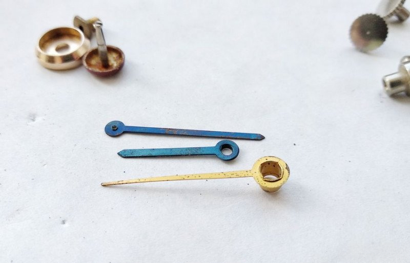
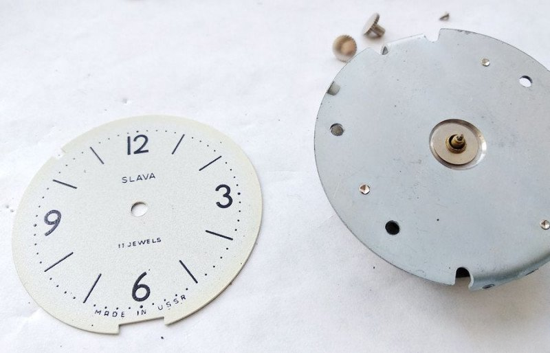
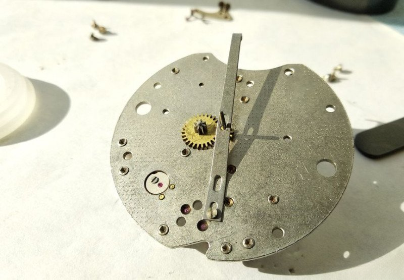
Let's remove the hands. The hour and minute hands come off as usual, but the alarm hand is mounted on its own special bushing. This construction is specific to alarm clocks.
The dial simply rests on the mechanism and is secured against shifting by a protrusion that fits into a slot on the dial.
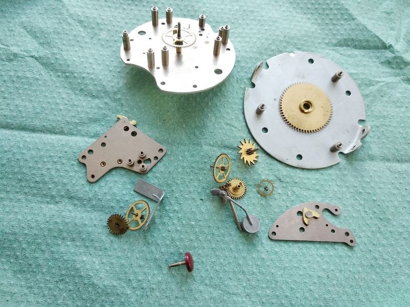
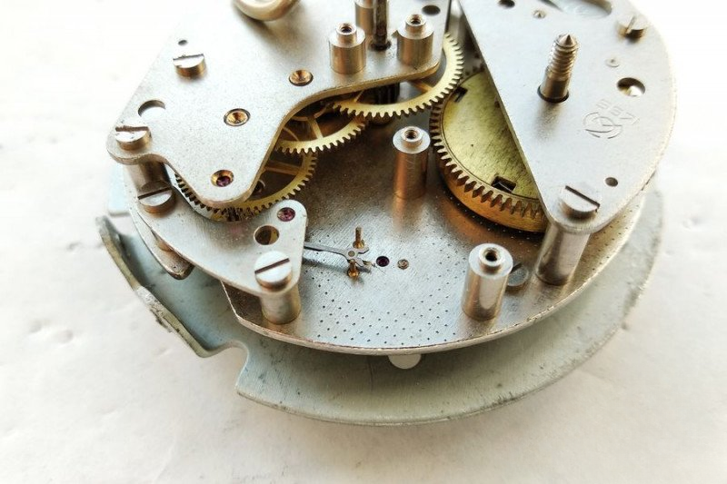
Now we can begin working with the core mechanism.
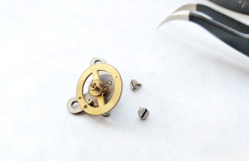
We start by removing the balance wheel. Everything looks normal here. We'll disassemble and service it properly before reinstallation, but for now, let's set it aside.
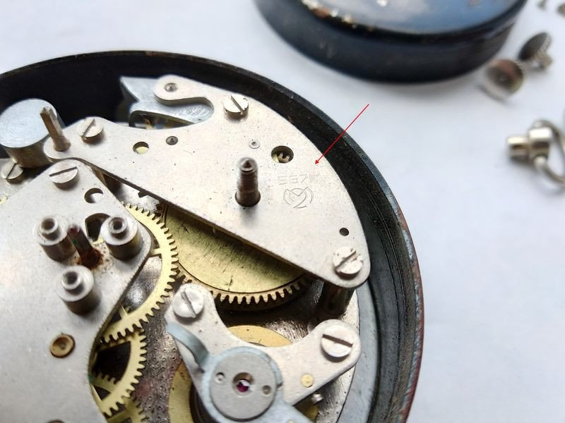
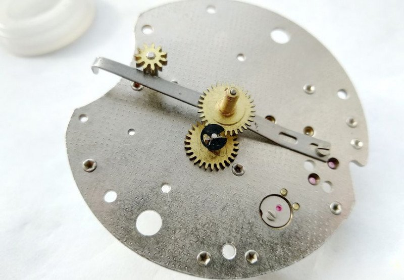
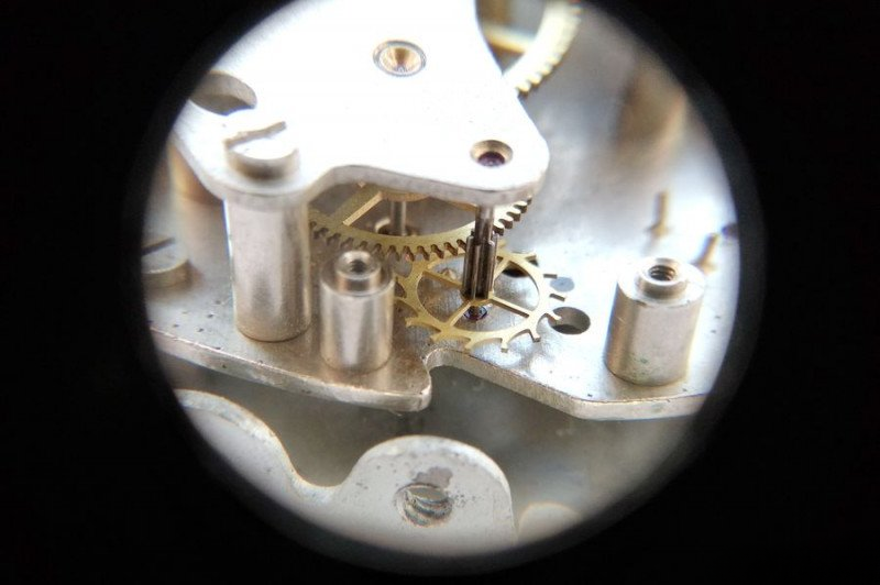
Next, we remove the anchor fork and its bridge. Before removing the anchor fork, we need to release the spring tension. There's a special lever on the ratchet for this purpose. We install the winding crown, hold it with one hand, and press the ratchet lever to release the mainspring barrel's ratchet wheel. That's all there is to it.
Now we can remove the anchor fork. Its dimensions correspond to the caliber, which has a diameter of 56mm - quite substantial for a clock mechanism.
We can now work on the train wheels. Let's remove the train wheel bridge of the clock's going train.
This is how the train wheel bridge looks from above.
And this is how it looks from below. Now we can clearly see the ratchet with its lever that prevents the spring from unwinding.
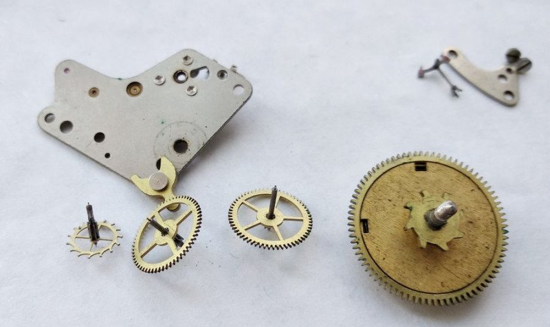
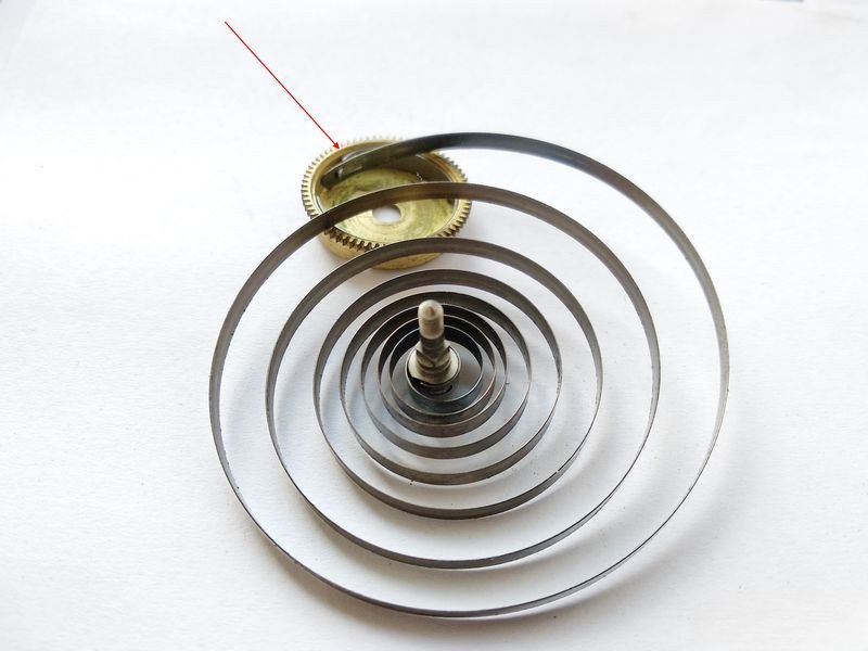
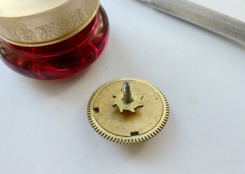
And here before us is the wheel train along with the going barrel with its ratchet wheel.
Let's remove the barrel and wheel train from the plate.
Let's open the barrel. I wonder what was used to lubricate it last time, and when? No matter - we'll clean it thoroughly and get it back to proper working condition.
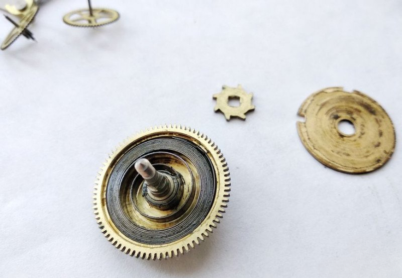
Now we extract the mainspring from the barrel. This is a standard but quite powerful spring. When working with it, I strongly recommend wearing safety glasses - better safe than sorry, as these springs can be quite energetic when released.
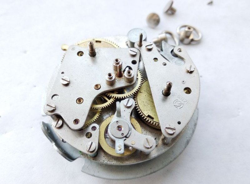
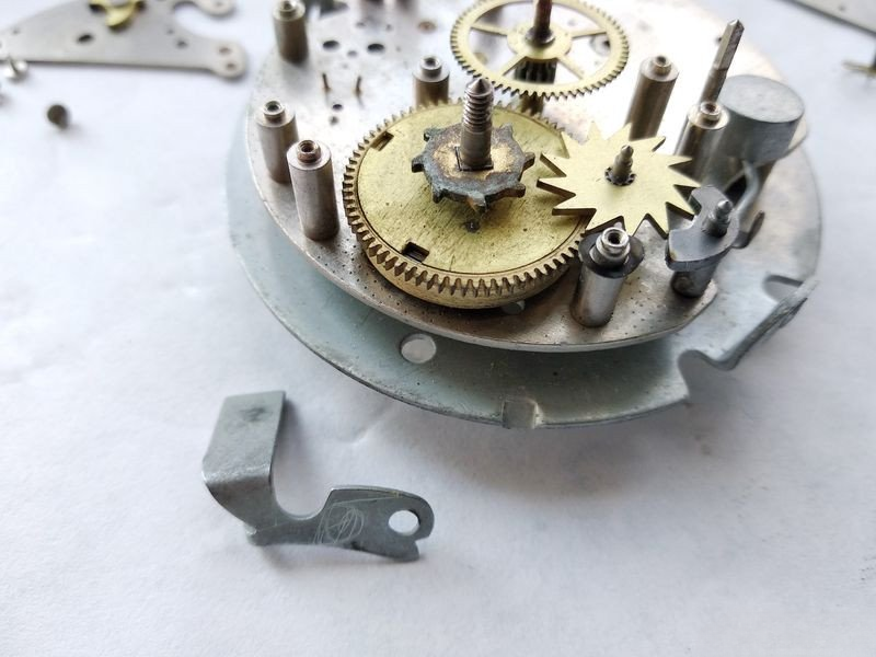
We're done with the going train side. Now let's turn our attention to the alarm mechanism.
We turn the mechanism to access the alarm side and remove the alarm mechanism bridge.
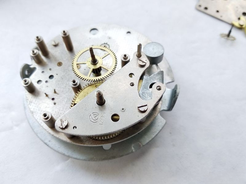
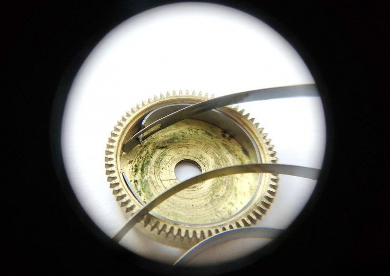
Here's what's revealed under the alarm mechanism bridge. We can see the alarm spring barrel with its ratchet wheel, and that interesting wheel that looks like a circular saw - that's the hammer fork wheel. There's also the alarm shut-off lever.
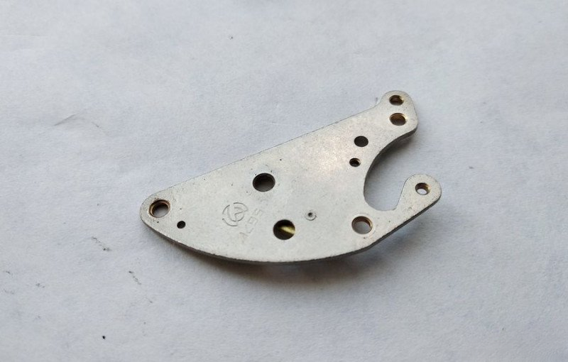
This is how the alarm mechanism bridge looks from above.
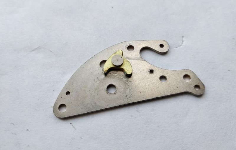
And this is how this bridge looks from below. Notice the ratchet that prevents the alarm spring from unwinding during winding.
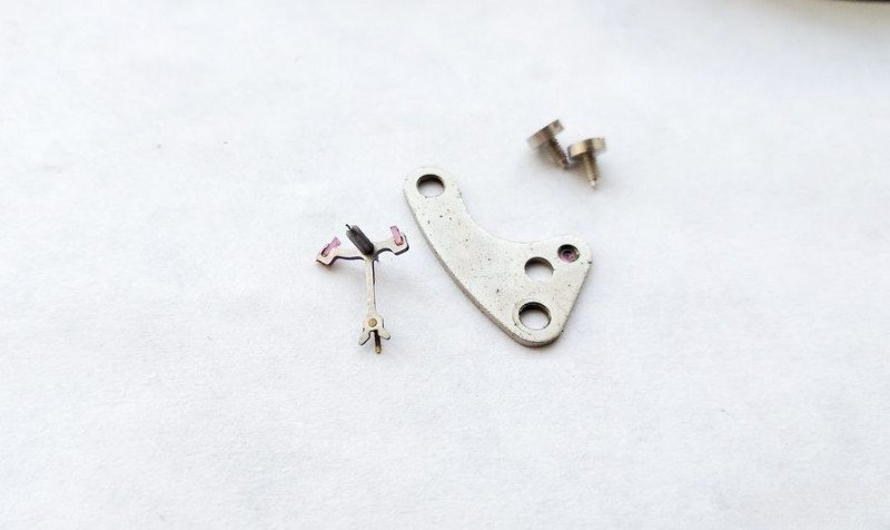
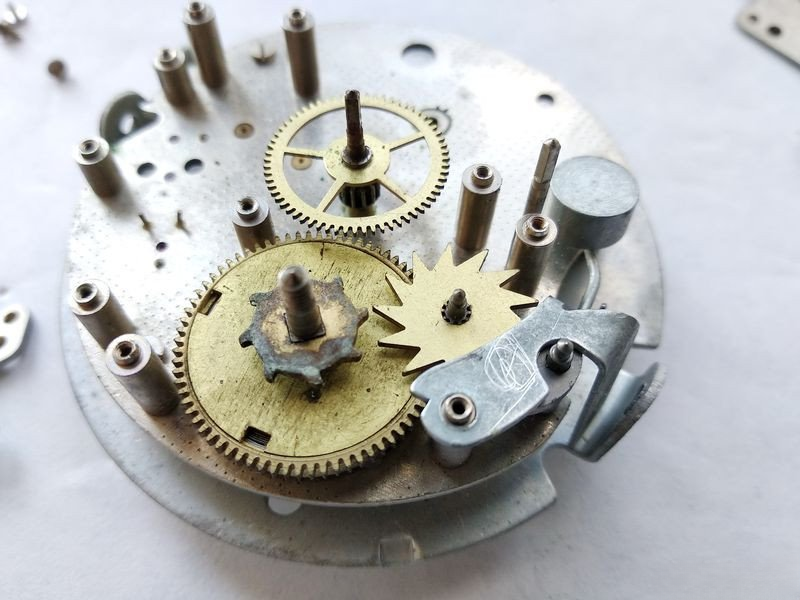
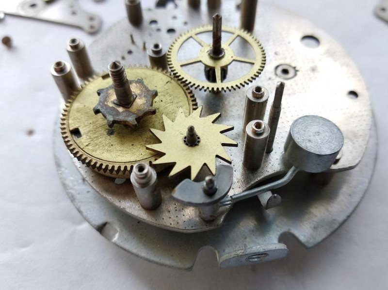
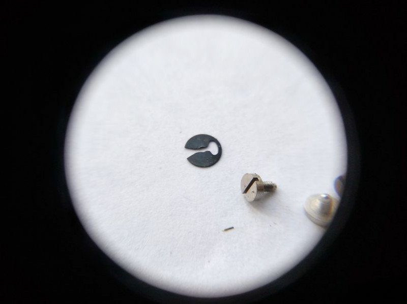
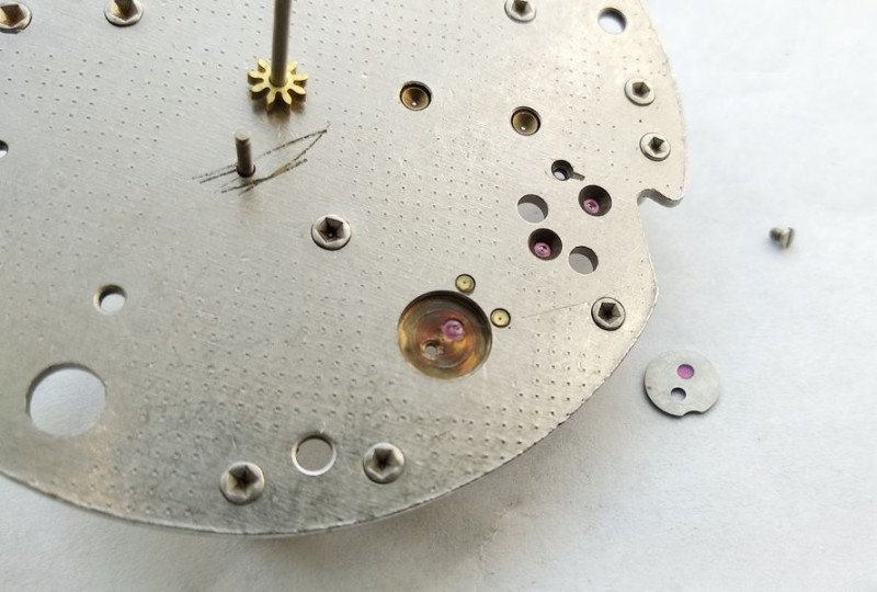
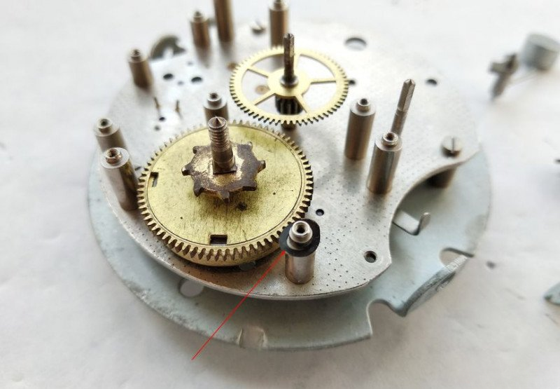
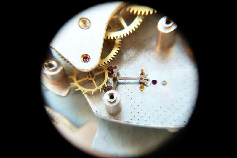
We remove the alarm shut-off lever. Now all the mechanism parts are clearly visible. But there's one very important detail that needs special attention.
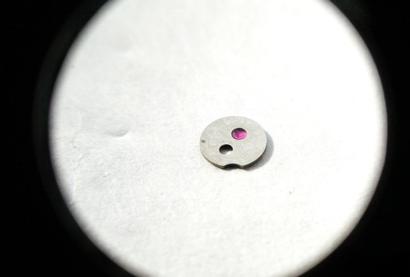
Here it is. Pay special attention to this specially configured spring washer. If this washer isn't installed or is positioned incorrectly, the alarm clock won't be able to be switched off, as the shut-off lever will move freely instead of turning with the required resistance. So be extremely careful with this washer - don't lose it!
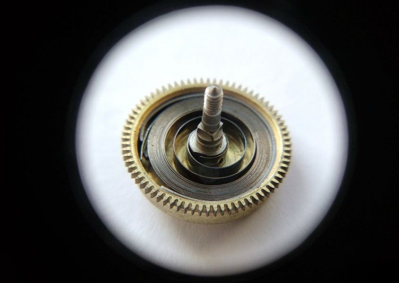
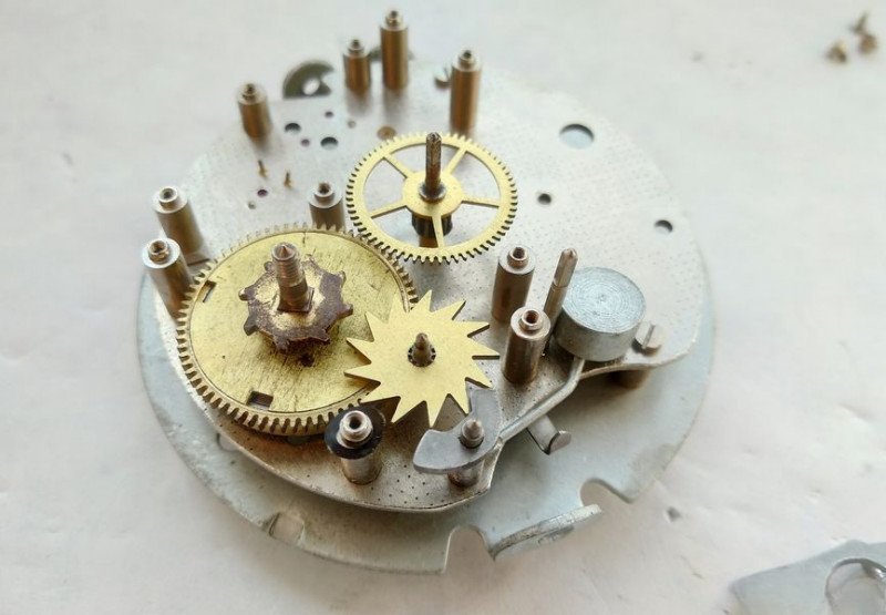
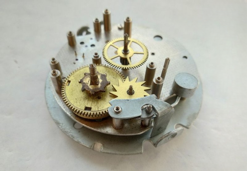
With the washer removed, we can examine the alarm mechanism in more detail. Before us is the alarm spring barrel with its ratchet wheel, the hammer fork wheel, and the hammer itself. The hammer assembly consists of a fork, axis, bracket, and the hammer mounted on it. If you look closely, you can recognize a simplified version of the familiar anchor mechanism here.
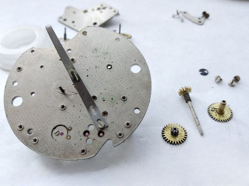
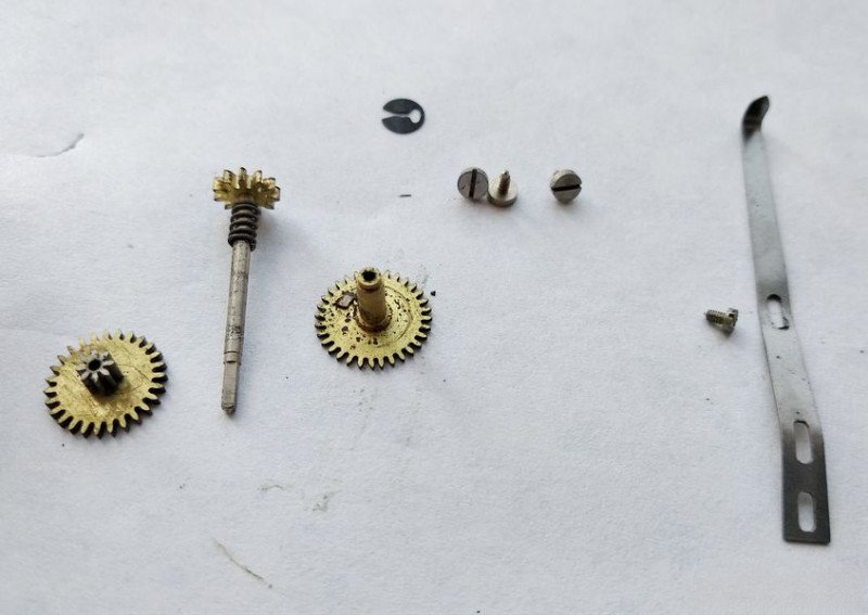
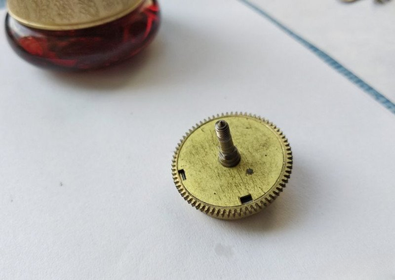
Let's remove the alarm mechanism components. Here we can get a good look at the hammer fork wheel with its pinion.
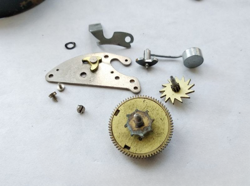
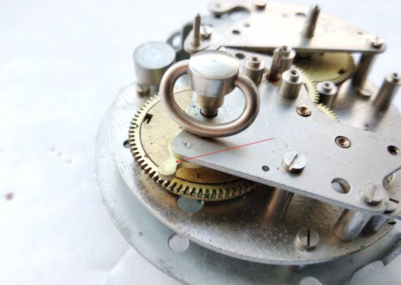
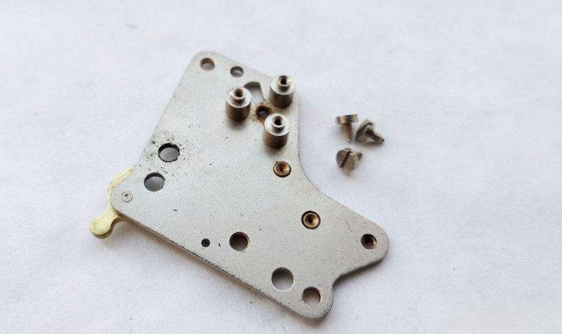
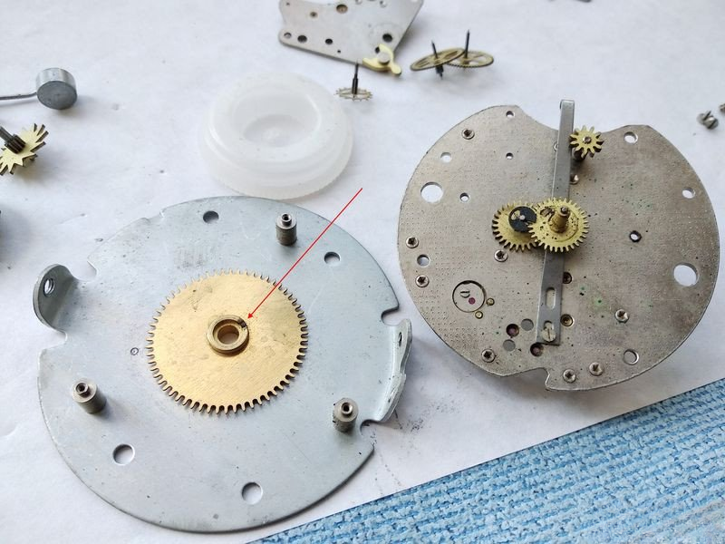
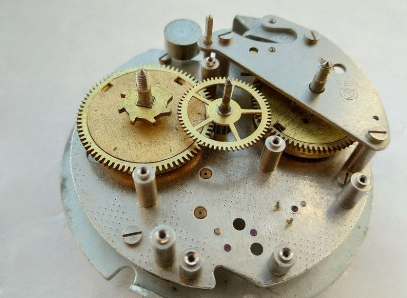
The plate is now free of mechanism parts. Let's disconnect the alarm wheel plate. We unscrew three screws around the perimeter...
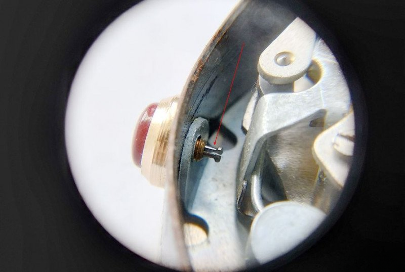
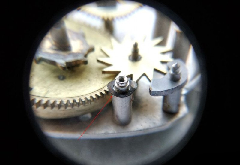
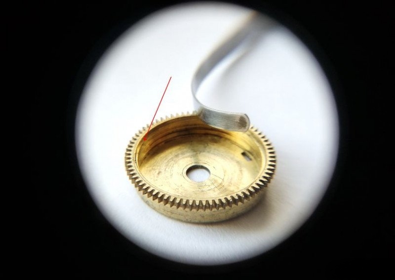
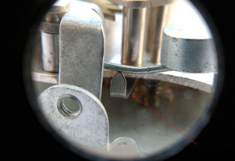
...and separate the alarm wheel plate. The bushing of this wheel accepts the stem of the alarm indicator hand. The wheel itself rotates with the hand via the alarm setting pinion. It remained on the plate, visible at the top right. Notice the slot marked with a red arrow. The hour wheel's tab enters this slot. When this happens, the stop spring - look to the right, that long vertical piece - moves away. This is how the alarm activation time is set.
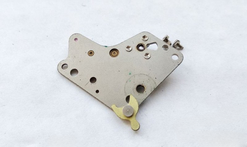
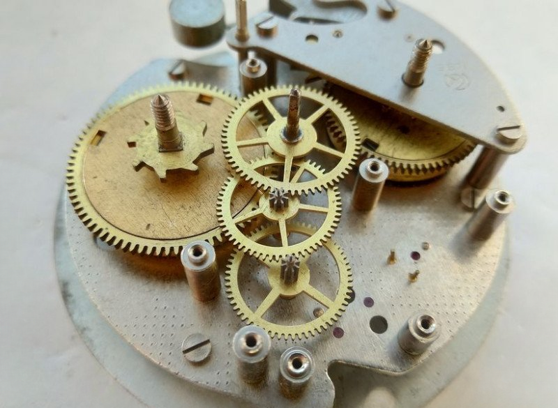
But let's continue disassembling the mechanism. Do you see the black retaining washer on the right of the plate? It holds the cannon pinion wheel in place. When the mechanism is disassembled, it prevents the hour wheel from falling off its axis. Let's remove this washer now.
Here's what it looks like.
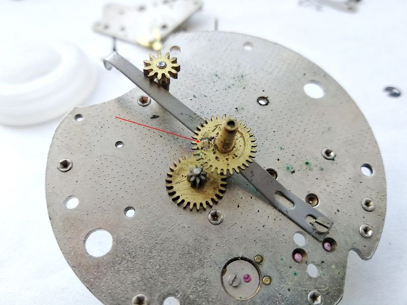
Now let's focus on the motion work side, in detail. The cannon pinion is now free from its retaining washer. We've already discussed the hour wheel's tab that activates the alarm mechanism (red arrow). Let's remove these parts.
The wheels come off freely, and the pinion axis isn't retained by anything.
However, to remove the spring, we need to loosen a screw. That's all. The parts are dismantled. From left to right - the cannon pinion wheel, the alarm wheel pinion with its axis and spring, the hour wheel, and the hammer spring. This spring is what holds the hammer's movement until the hour wheel's tab drops into the alarm wheel's slot. When the spring releases the hammer, the alarm starts ringing. By the way, adjusting this assembly can be quite intricate.
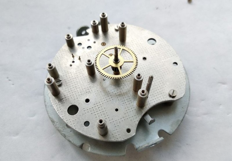
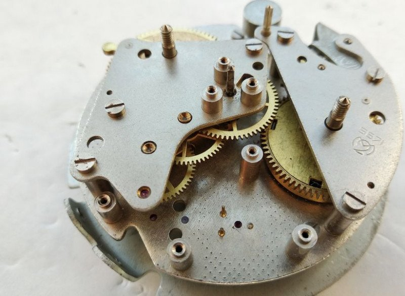
The plate is now free of mechanism parts. The center wheel with its minute pinion is press-fitted and we won't disassemble it as there's no necessity.
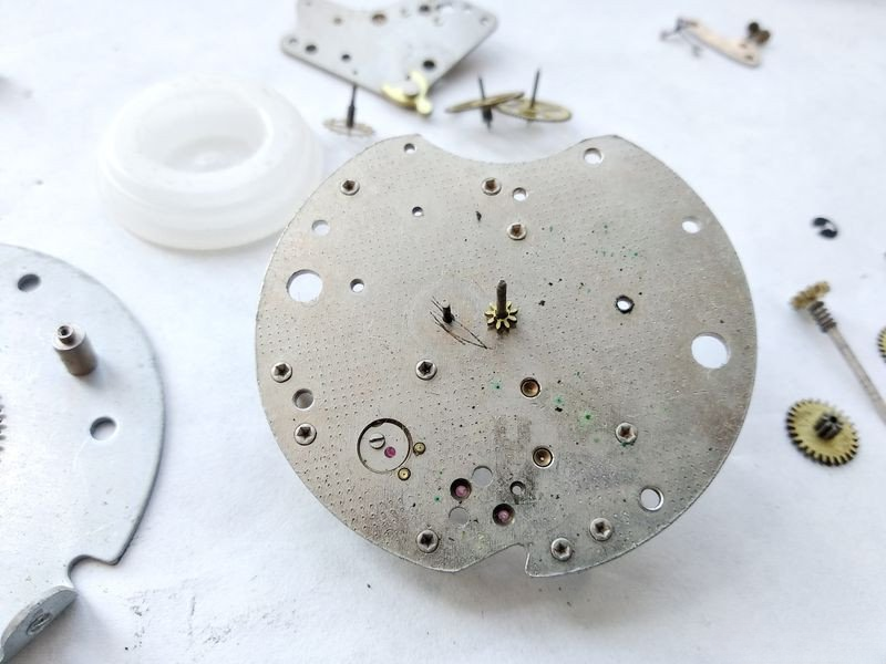
At this stage, we can consider the mechanism disassembled. Why stop here? The center wheel assembly is press-fitted, and attempting to disassemble it without consequences can be quite challenging. Therefore, we'll clean it together with the plate.
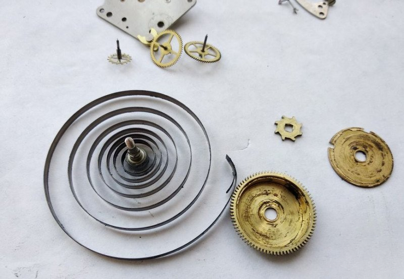
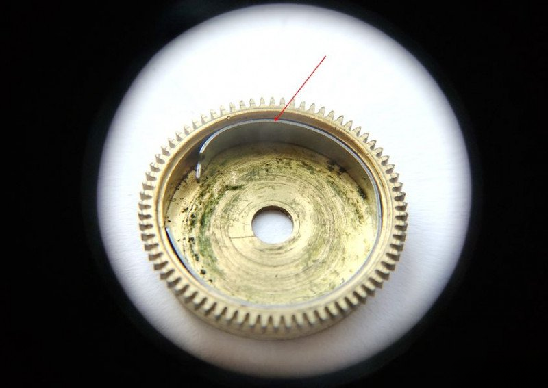
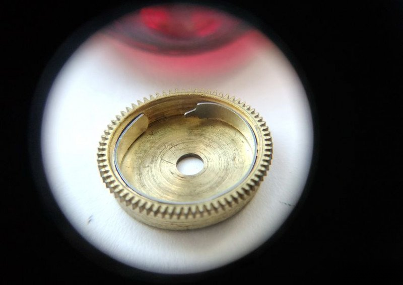
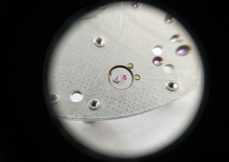
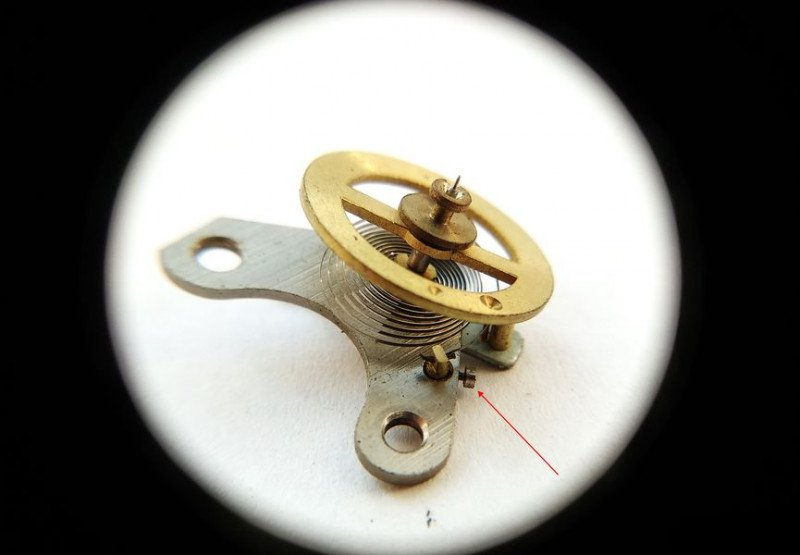
However, one of the most crucial components of the alarm clock remains unexamined. As you might have guessed, I'm talking about the alarm barrel. We'll dedicate more time to it because... well, you'll immediately understand why when we start disassembling it. Let's look. The barrel cover is open, the spring removed. But what's that interesting feature that the red arrow is pointing to?
Let's look closer... it's a friction device! Yes, exactly the same type used in automatic watch barrels!
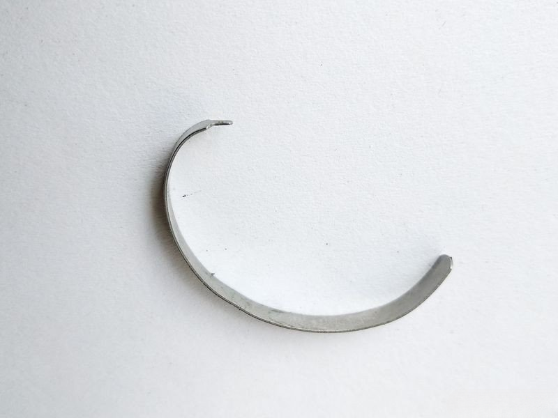
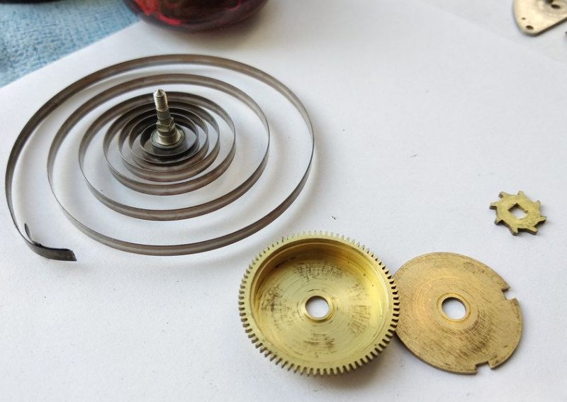
Can you see how it's designed? Inside the barrel, there's a circular spring that presses tightly against the barrel wall. The spring has a tab that engages with the mainspring through a slot. If you continue winding the spring after all coils are fully wound, the spring will pull the friction device and it will simply slip against the barrel wall. This way, it's impossible to break the spring.
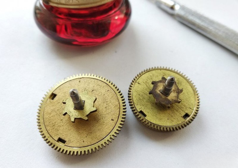
Let's remove this part from the alarm barrel. Here it is before us. And the first thing we start with when cleaning the clock is precisely these barrels. We wash out all possible contamination from the barrels and springs, clean and dry all parts thoroughly.
Here they are, our power sources, after acquiring a decent appearance.
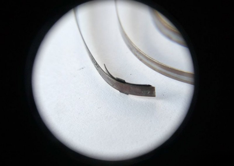
Let's examine the spring construction in detail. This is the tail end of the alarm mechanism spring. This slot engages with the friction spring's tab in the barrel.
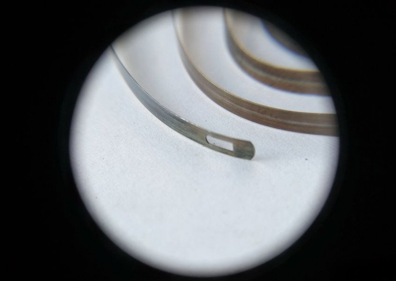
Let's examine the going train mainspring's tail end. Here we see nothing unusual - a standard sword-shaped cap. So when you feel resistance while winding the going spring, it's better to stop applying force to avoid tearing the cap from the spring. However, when winding the alarm spring, we don't face such a risk thanks to the friction device.
Now let's assemble the alarm barrel. We lubricate the barrel wall. Here we'll use thicker oil. Clock oils come in different viscosities for different applications.
We install the friction safety spring back into position.
We place the spring in the barrel and lubricate it with spring oil.
Close the barrel cover. Done.
Now it's time for the going barrel. Here everything is standard, as in regular clock barrels.
We install the spring and lubricate it.
Close the barrel cover and mount the ratchet wheel on the barrel arbor.
The barrels are serviced and ready for installation. But we still have quite a bit of work ahead of us.
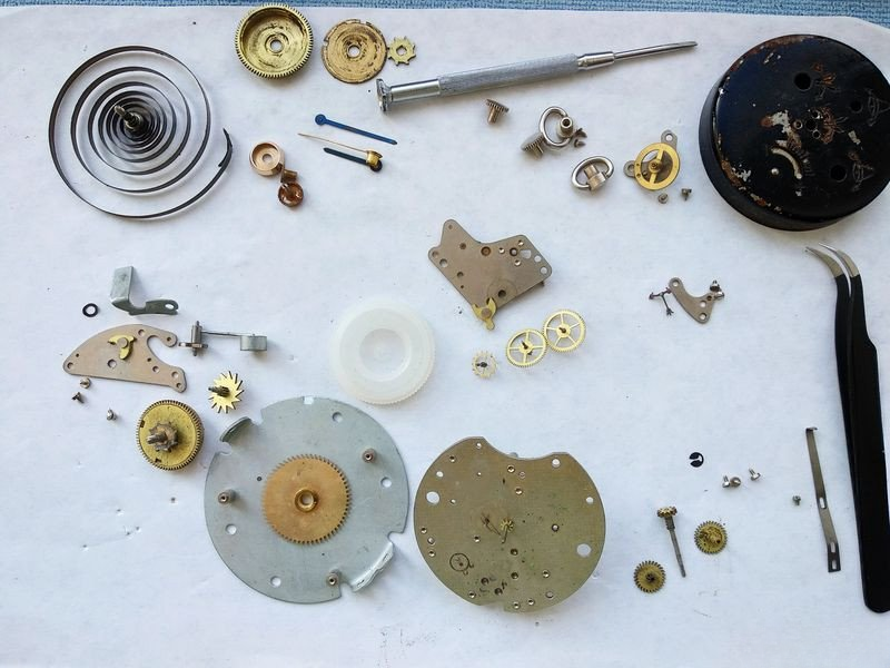
First and foremost, we need to thoroughly clean the remaining clock mechanism parts. We need to get them to this condition - shining and pristine.
With cleaning complete, before installing the parts, let's service the balance jewel assembly. We'll thoroughly clean the hole jewel and lubricate the cap jewel.
Let's remove the cap jewel and clean the setting with a cotton swab, blow out any lint, and finish cleaning with a pith wood.
Clean the jewel and apply a drop of lubricant. Let's treat our clock to some Moebius oil. After all, this is the balance we're working with.
Assemble the jewel setting.

Now it's time for the cannon pinion wheel...
...and the hammer spring.
Next, we return the hour wheel to its place and install the cannon pinion retaining washer, which also prevents the hour wheel from jumping off.
We install the alarm wheel plate, securing it to the plate posts with three screws. That's complete.
Moving on to assembling the alarm mechanism.
We install the alarm barrel. Don't forget about the friction washer for the hammer blocking lever.
Then we return the hammer fork ratchet wheel and install the hammer itself.
Install the hammer blocking lever.
Check the adjustment of the alarm release spring. We'll return to it later as adjustment might be needed.
And cover the alarm mechanism with its bridge. That's done.
Moving to the going train assembly. We install the mainspring barrel with its ratchet wheel.
We arrange the wheel train and install the wheels. At this stage, I haven't installed the escape wheel. Assembling five arbors under one bridge can be challenging. Therefore, I'll now cover three wheels with the barrel...
Then slightly loosen the screws, just enough so the train doesn't fall apart, and position the escape wheel. It works in jeweled bearings, which is excellent!
There we go. The escape wheel is in place. Let's check the freedom of the wheel train movement, known as 'end shake'.
Now we install the pallet fork.
Cover the fork with the pallet bridge.
A small digression here. The debate about whether to lubricate pallet fork pivots has been going on for three hundred years. Well, let me tell you what happened. I lubricated the fork pivots. The clock ran for a while, then stopped. When I investigated, I found the balance had a weak amplitude. I tried different viscosity oils on the fork. Still not right. Cleaned it, tried again, put it back dry. The clock now runs precisely and accurately. The amplitude is sufficient, the beat is stable. So 'experience, son of difficult mistakes' has been useful to me. And to the reader too. In short, experimentation is necessary.
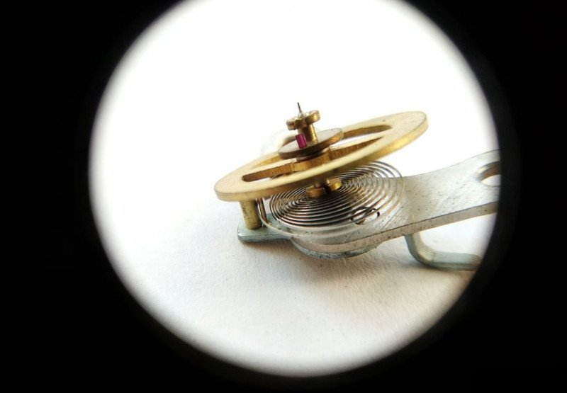
The impulse on the fork is good. Time for the balance wheel. Here's a piece of work. First, notice that the balance staff is secured with a screw. In later modifications, it was friction-fitted into the balance cock, making it very inconvenient to adjust the hairspring during maintenance.
Here you can clearly see the impulse jewel, the balance staff pivot that clearly needs good cleaning, and the regulator pins between which the hairspring is stuck in residue of something unidentifiable.
Remove the balance wheel.
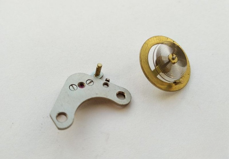
This is the view of the balance cock from the regulator side.
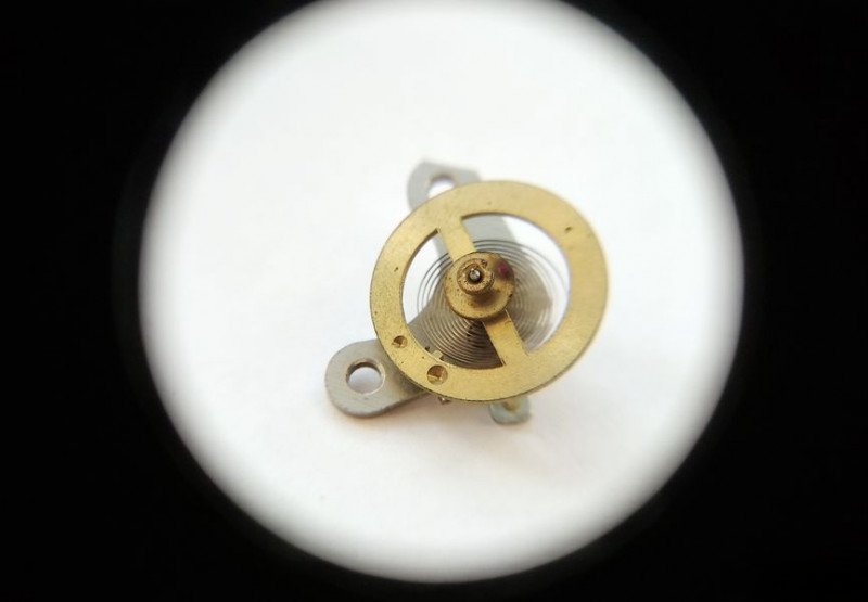
And install the balance in the mechanism. The fork catches it and the balance starts oscillating. Well, as they say, success!
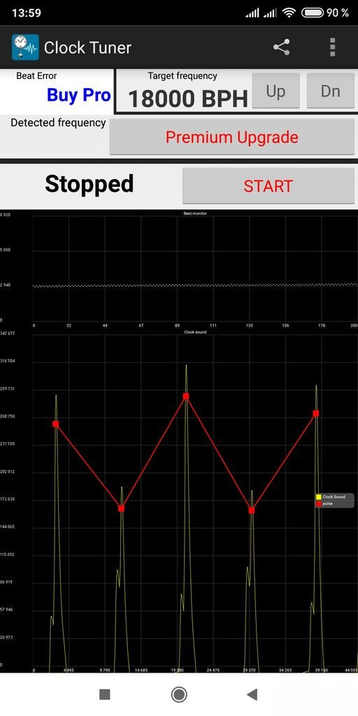
The final test shows perfect linearity - work well, my friend. Wake me up tomorrow at seven o'clock!
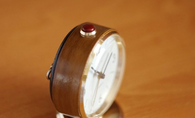
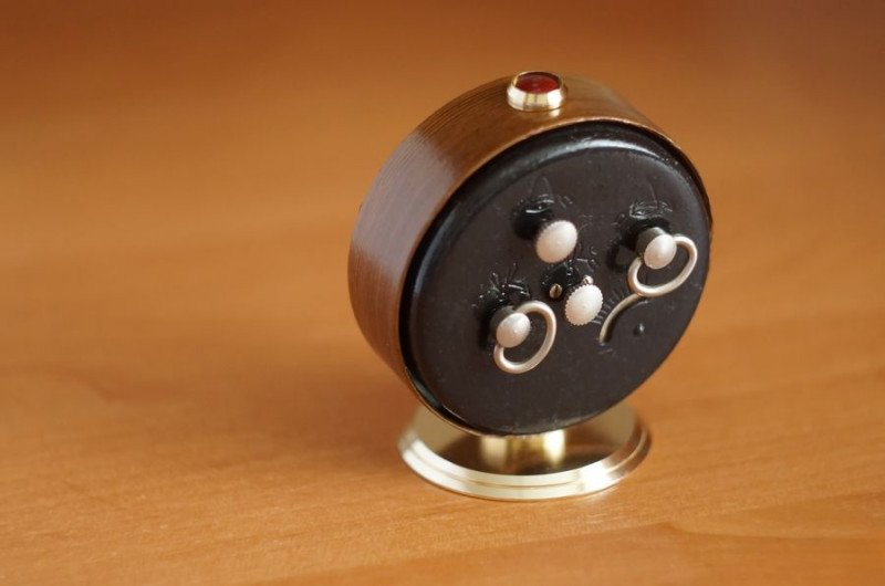
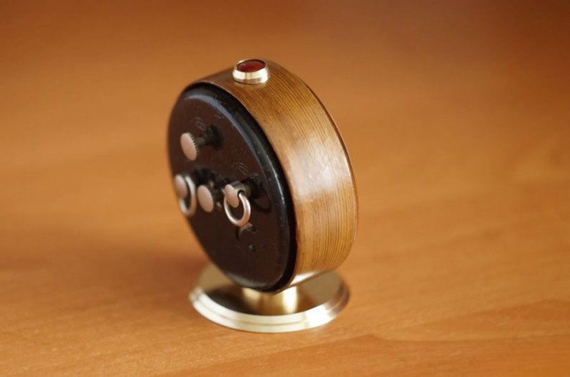
For the case restoration, I decided on a creative approach. Using wood-grain effect film and careful refinishing of the metal parts, we've achieved a complete transformation of the clock's appearance: