Zarya 2008 Caliber Service Guide the Yunost Soviet Youth Watch

Servicing the Yunost on the Zarya 2008 Caliber and Its Intermediate Shock System

Servicing the Yunost on the Zarya 2008 Caliber and Its Intermediate Shock System

Servicing the Yunost on the Zarya 2008 Caliber: A Soviet Youth Watch and Its Intermediate Shock System

"The most ordinary watch often hides the most instructive engineering. You only have to open it and look without prejudice."
— Igor

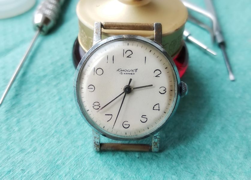
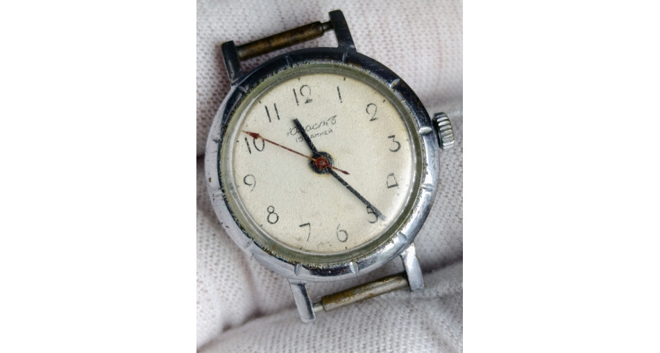
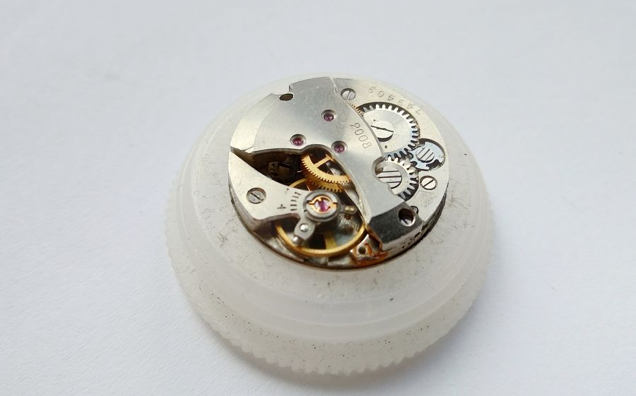
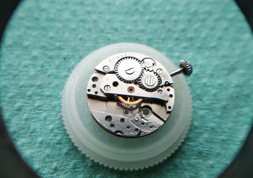
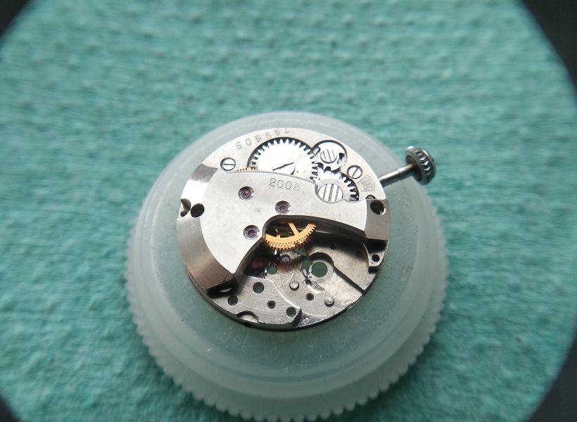
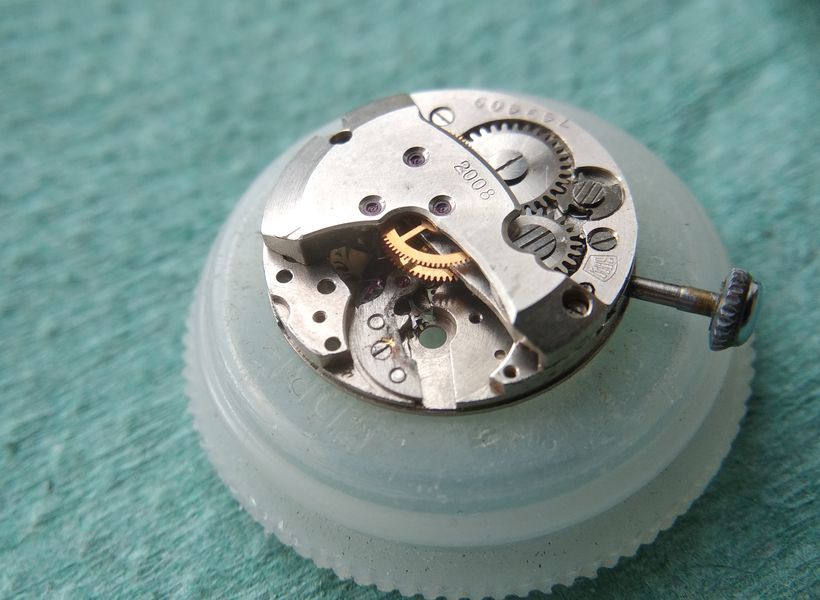
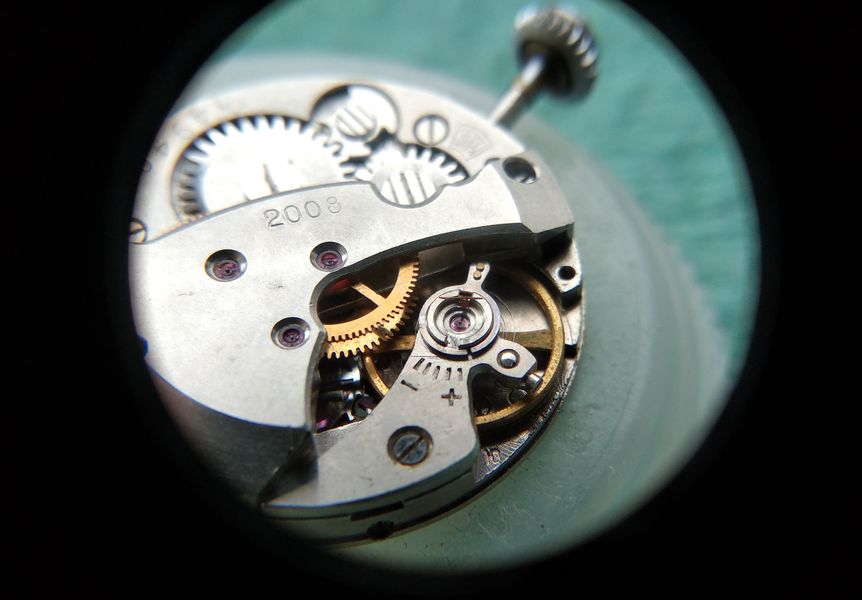
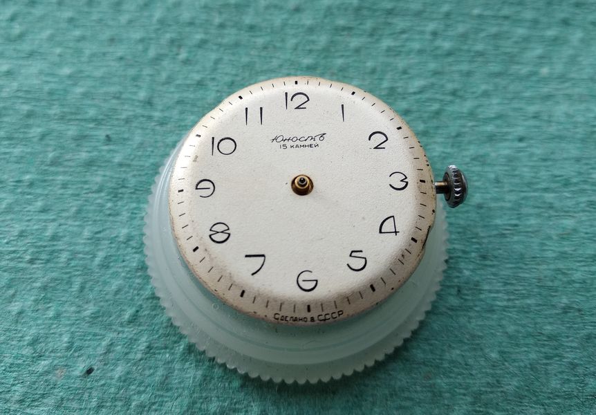
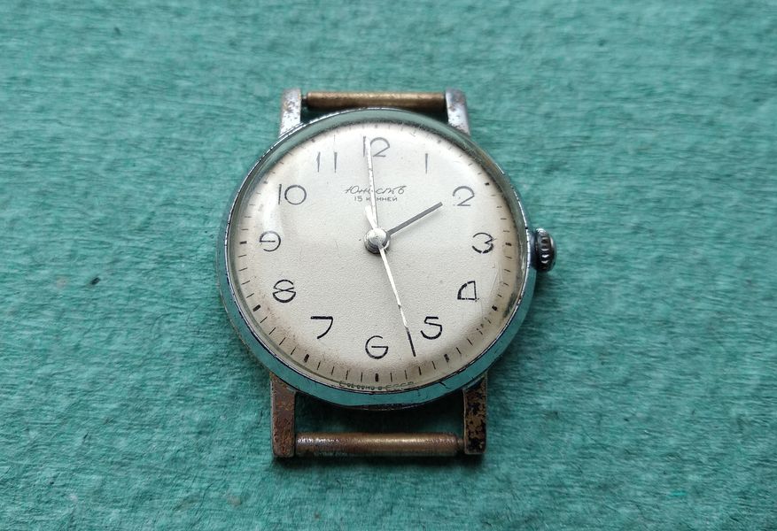
Few Soviet watches were taken less seriously than the ones marked Yunost — literally "Youth." They were inexpensive, utilitarian timepieces, the kind handed to a student or a young worker as a modest gift, worn hard, and rarely cared for. Yet the movement inside this particular example, a Zarya caliber 2008, is far more interesting than its humble reputation suggests. The GOST designation that ends in "08" is usually read as shorthand for a center-seconds movement without shock protection — no Incabloc, in other words. As we shall see, that reading is not quite the whole truth, and the reason lies in the unusual construction of the balance bushings, which we will examine in detail once the watch is on the bench.

Front of a worn Yunost wristwatch with a silvered dial reading Yunost and 15 jewels, in a battered chrome case
The patient as received: a Yunost dial marked for fifteen jewels, the chrome plating largely worn from a case that has clearly seen decades of daily wear.

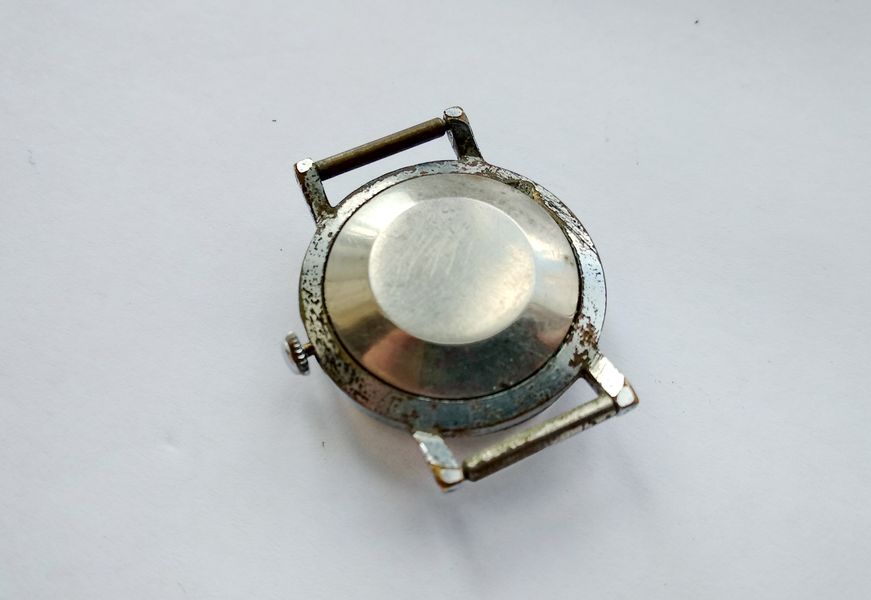
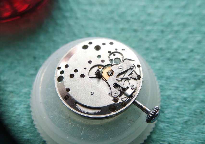
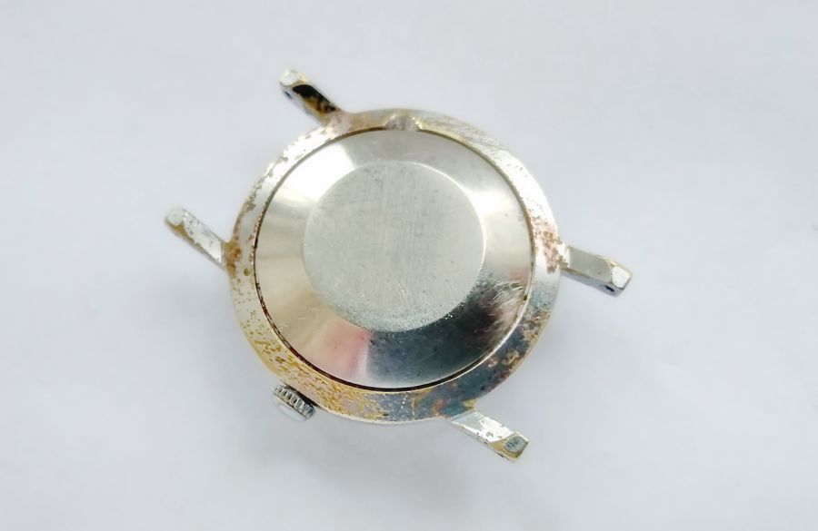
The dial survived surprisingly well. The case did not. This is the typical fate of these watches: the movement is sound and the face is presentable, while the plating has flaked down to the brass. None of that matters for what we are here to do, which is to take the movement completely apart, clean it, replace a broken component, and put it back together with proper lubrication.

A Humpbacked Movement in a Domed Case

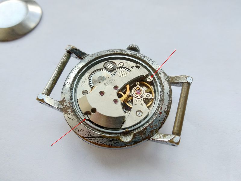
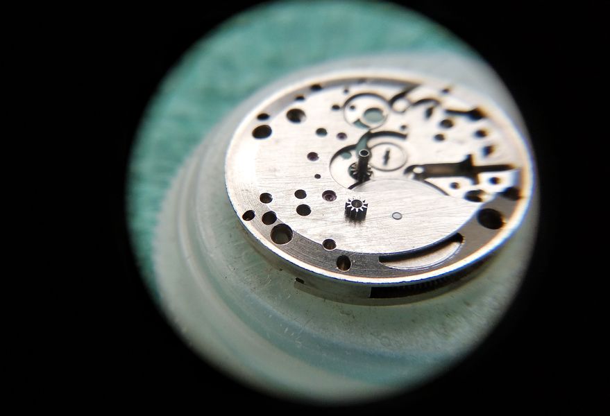
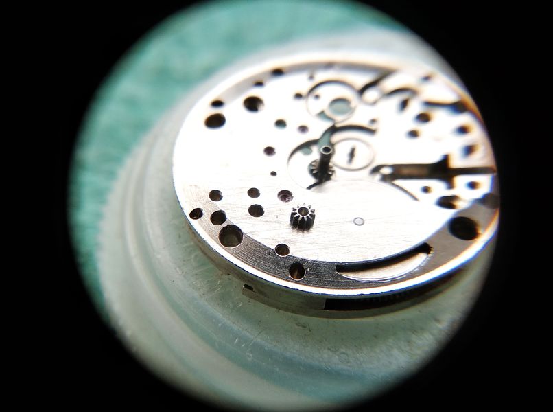
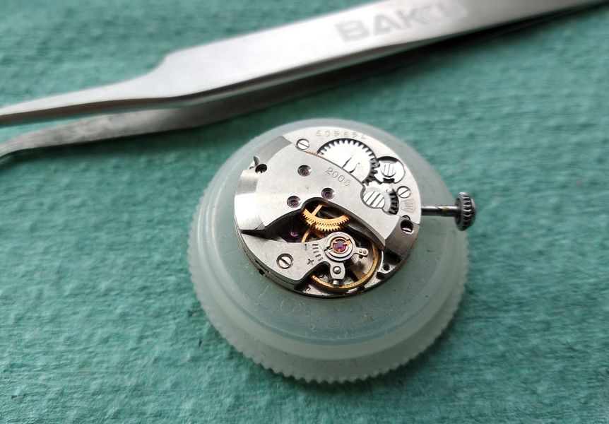
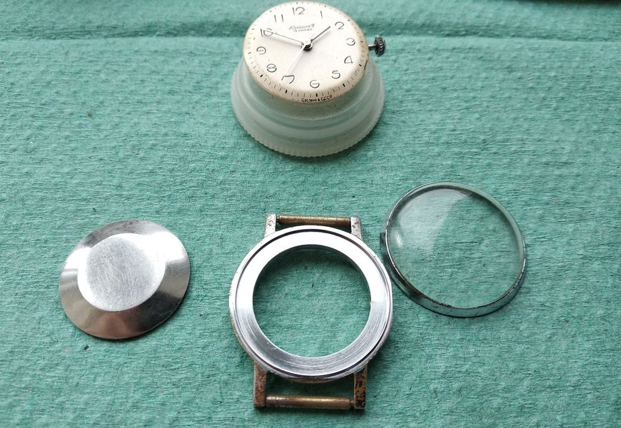
The back of the watch is closed by a convex snap-on cover — a "clapper" back, in the workshop slang. The dome is not decorative. It is there because the movement underneath is what watchmakers of the period called "humpbacked," tall enough that a flat back simply would not clear it.

Rear three-quarter view of the chrome watch case showing the convex domed snap-on case back
The convex snap-on back. The bulge is dictated by the height of the movement rather than by styling — a practical solution to a tall caliber.

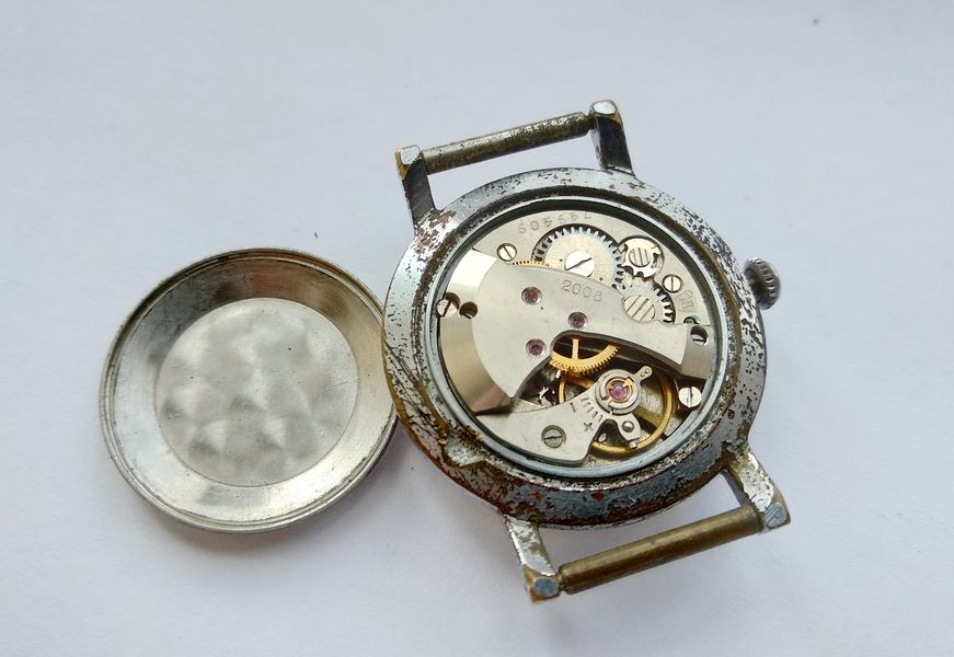
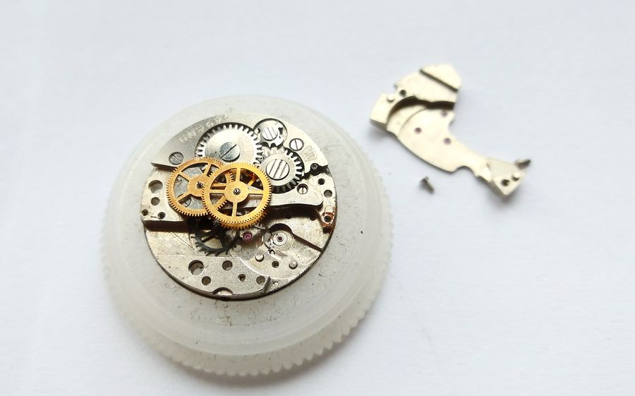
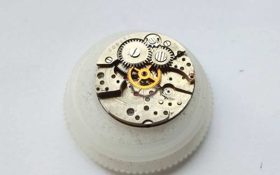
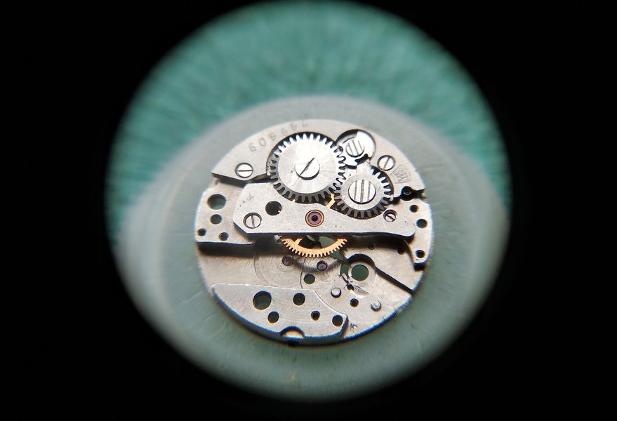
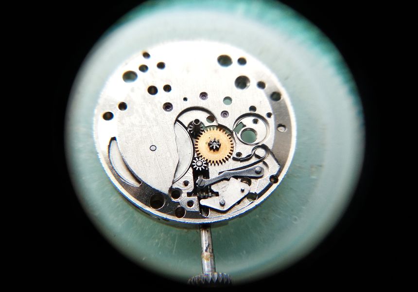
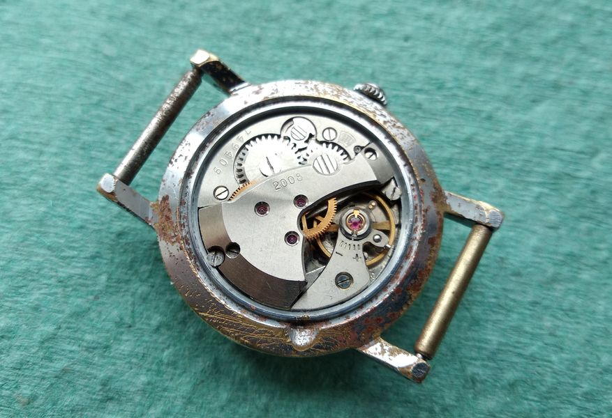
Pry the cover off and the reason becomes obvious. The gear-train bridge rises into a pronounced hump, the highest point of an unusually multi-tiered layout.

Watch case opened with the domed back removed, exposing the Zarya 2008 movement with its raised gear-train bridge
Back open. The caliber number 2008 is legible on the plate, and the gear-train bridge stands proud of everything around it — the "hump" that gives the design its nickname.

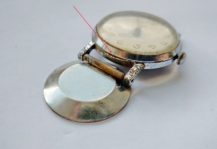
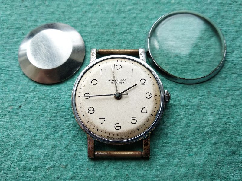
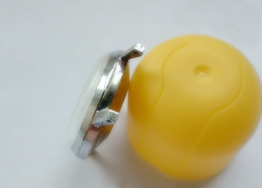
Before disturbing the movement, a small detail of the case deserves notice. The glass bezel carries a flat — a deliberate facet ground into the rim — and it is positioned directly beneath the lower lug.

Close view of the crystal bezel rim showing a ground flat positioned under the lower lug
The flat on the crystal bezel sits under the lower lug, where the strap hides it. A tidy bit of industrial design that keeps the feature from disrupting the round profile.

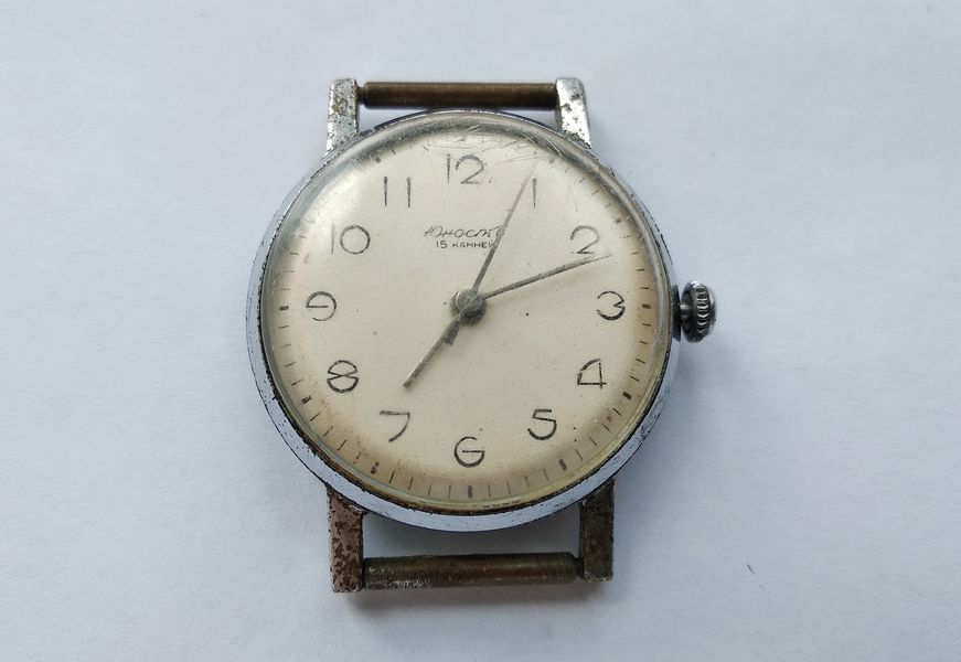
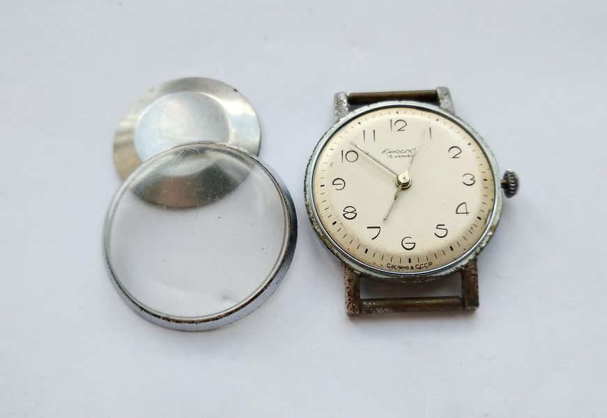
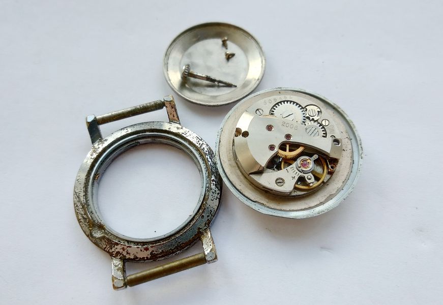
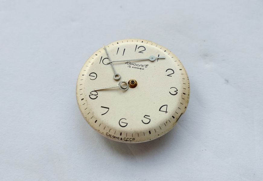
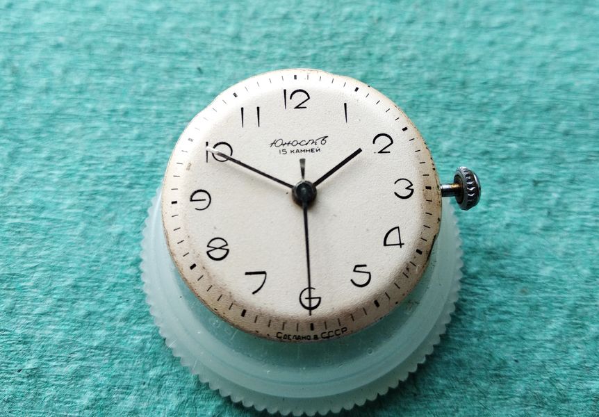
The bezel lifts away together with the crystal. The acrylic is badly scuffed but salvageable; we will polish it later. The dial, by contrast, is a pleasant surprise.

Crystal bezel and scratched acrylic crystal lifted off the watch, exposing the dial
The bezel and its tired crystal come off as a unit. The acrylic will be restored; the silvered dial beneath it is in genuinely good order.

Two case screws hold the movement captive. Back them out and the movement is free to leave through the front.

Movement retaining screws in the case being pointed out before removal
The two retaining screws. With these out, the movement will drop forward out of the case once the stem is released.

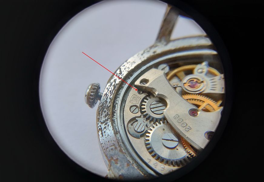
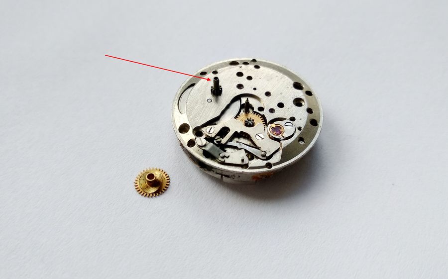
Releasing the stem is the only mildly awkward step. The setting-lever release is tucked into a deliberately inconspicuous spot — but a hidden button is no match for someone who knows where to press.

The concealed stem-release button on the movement being indicated with a tool
The stem release is hidden away in an unobvious location. Press it, and the winding stem withdraws cleanly.

With the screws out and the stem pulled, the movement comes out of the case without a fight. So far the disassembly is going exactly to plan.

Bare movement removed from the case and resting dial-up on the bench
Movement out of the case. Everything to this point has been straightforward — the real work begins with the hands and dial.

Removing the Hands and Dial

To lift the hands without scarring the dial, the whole dial is first covered with a sheet of thin film. This is an old and reliable trick.

The dial covered with a sheet of thin protective film before the hands are removed
A film laid over the dial protects the silvered surface and, just as importantly, controls where the hands go once they let loose.

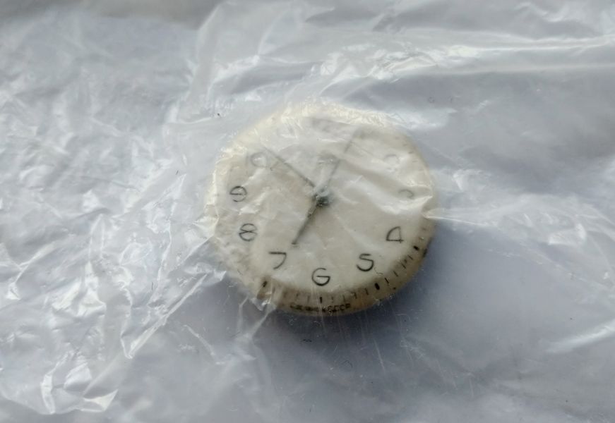
The hands are then levered up through the film with tweezers. The point of the method is that the hands do not spring off across the bench — they stay trapped under the film, exactly where you can find them.

Tweezers lifting the hands through the protective film covering the dial
Levering the hands up through the film. Because the film catches them, none of the small parts can flick away and vanish.

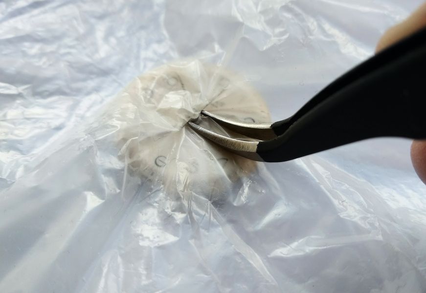
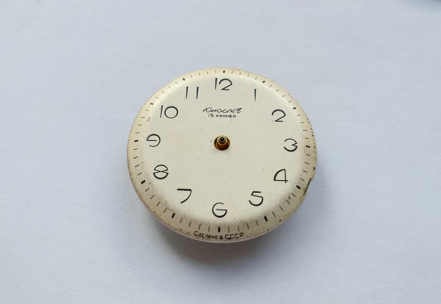
And that is the result: three hands lifted, none lost, the dial untouched.

The watch hands freed and resting on the protective film over the dial
Hands off, dial unmarked. A simple sheet of film turns a nervy operation into a routine one.

Now the dial itself. It is held by dial-foot screws on the side of the movement.

The dial being lifted away from the movement
The dial comes away to reveal the dial-side plate and the motion work beneath.

The dial-foot screws on the flank of the movement only need to be loosened, not removed entirely. Once the dial is off, they are simply driven back in so they cannot be lost.

Dial-foot retaining screws on the side of the movement being loosened with a screwdriver
The dial feet are secured by side screws. Loosen — never fully extract — them, then run them back in for safekeeping after the dial is clear.

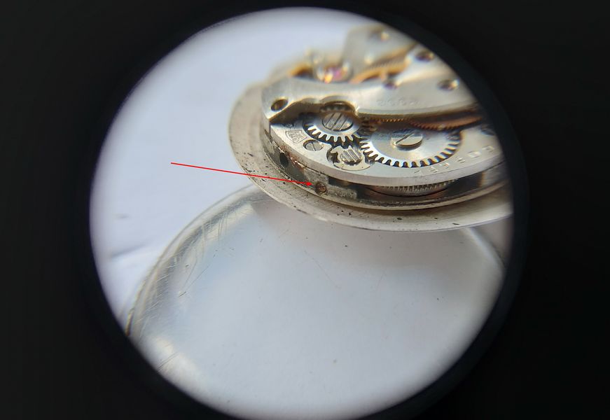
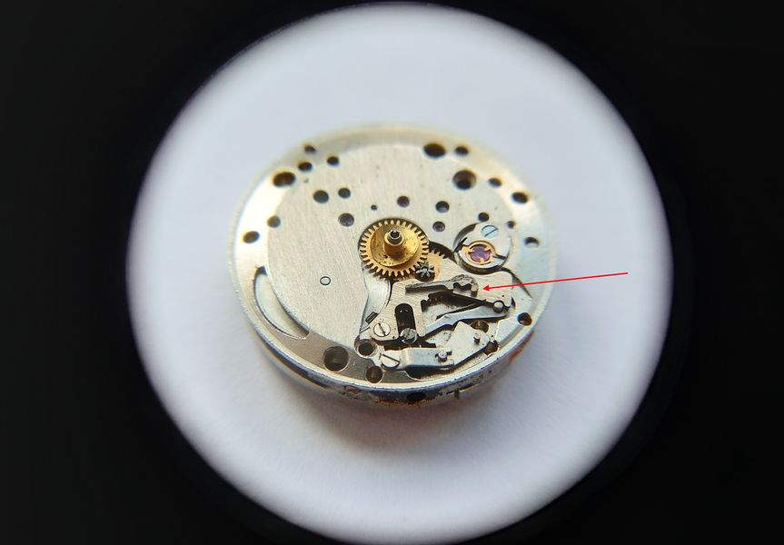
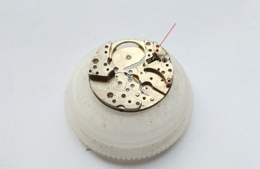
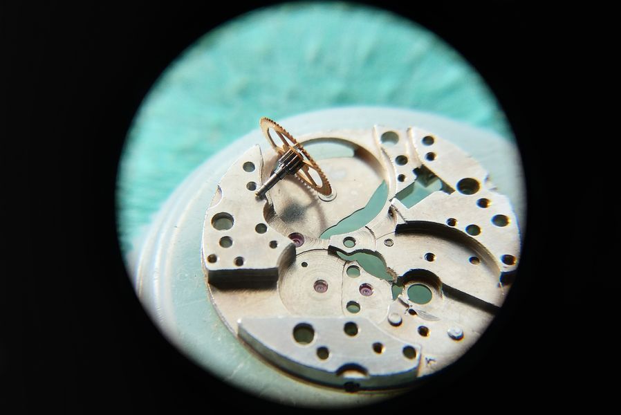
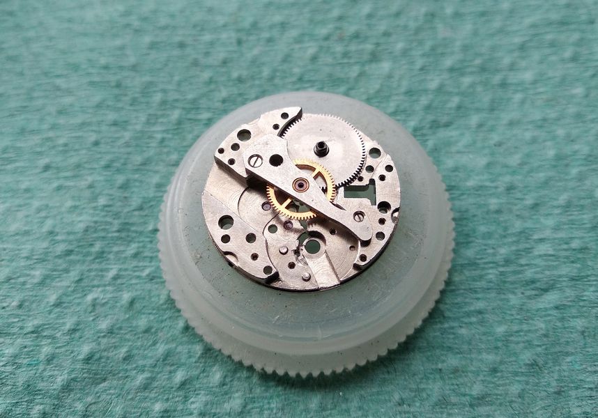
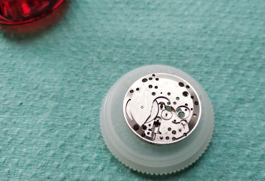
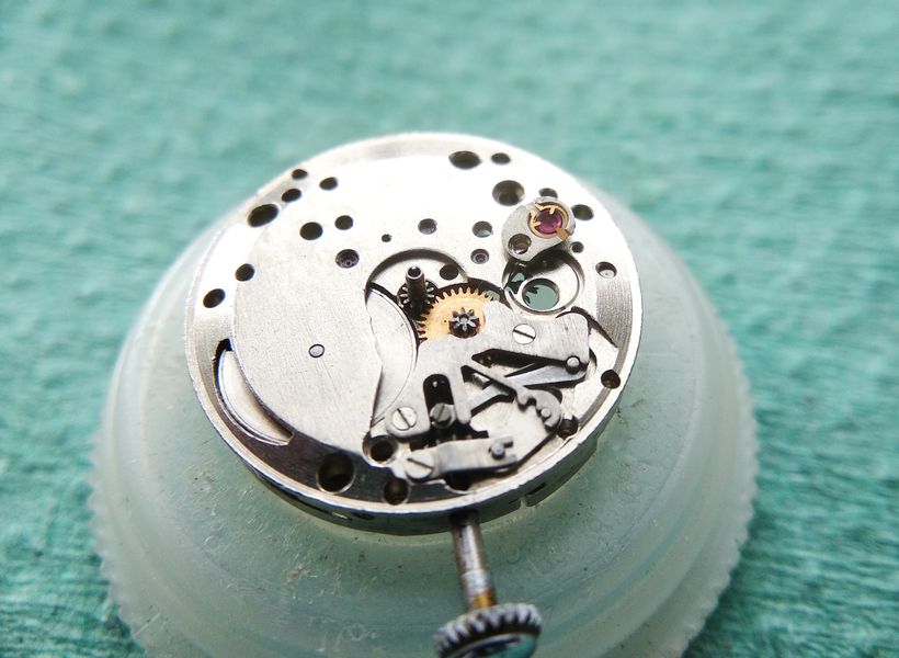
With the dial off, the dial-side condition is reassuring. The silvered dial will clean up beautifully. The first real trouble, however, is right here.

Dial-side of the movement exposed after dial removal, in good overall condition
The dial side is clean and intact, and the dial itself — silver-plated — will respond well to cleaning. One component, though, has failed.

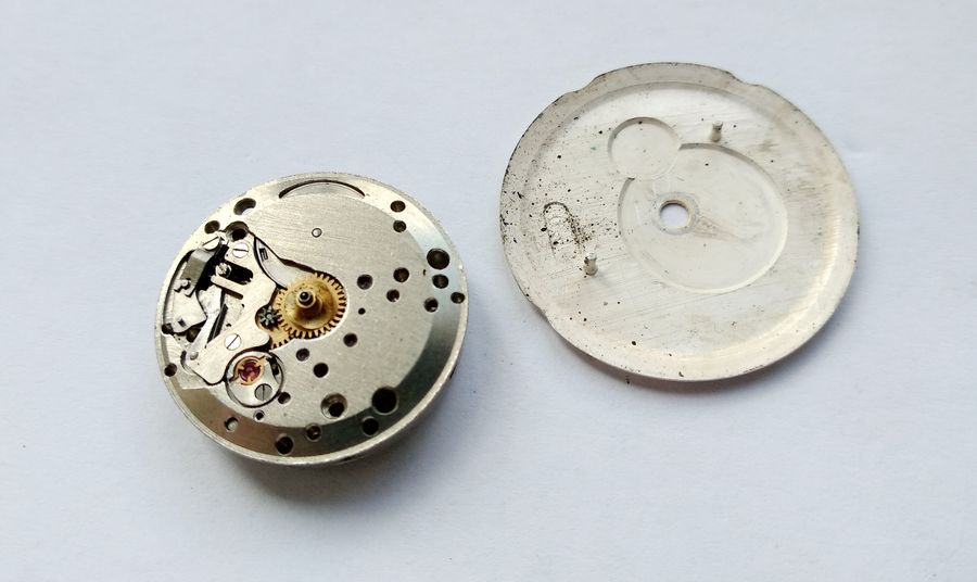
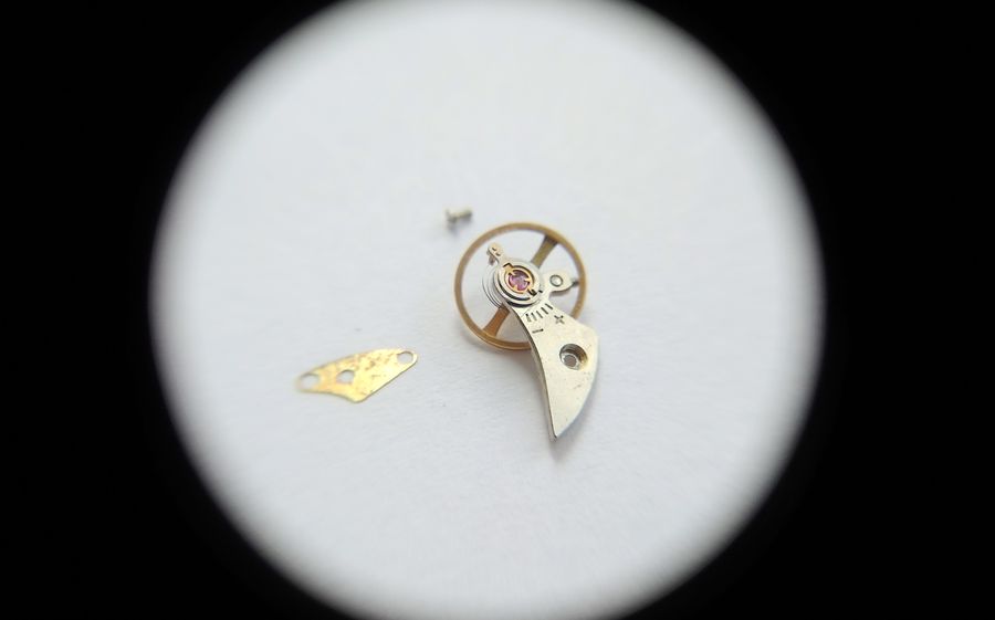
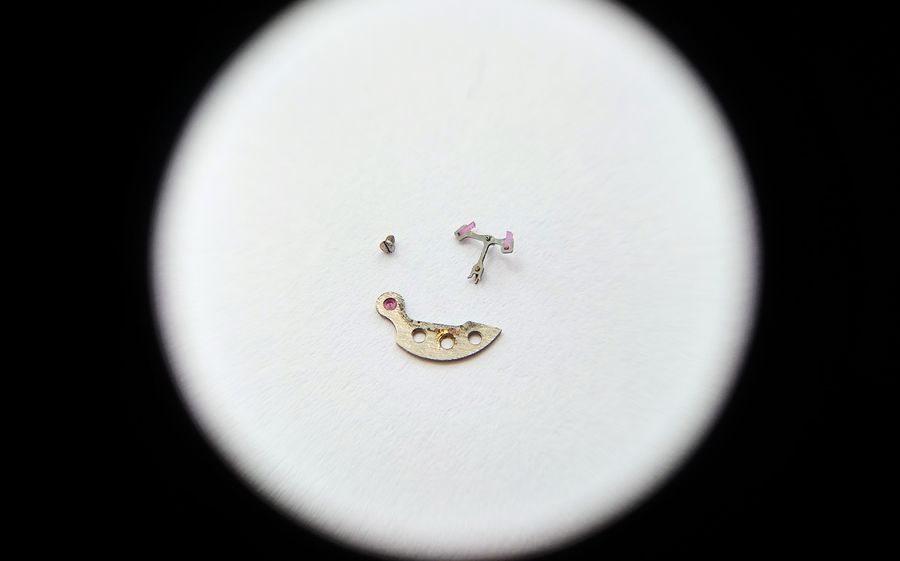
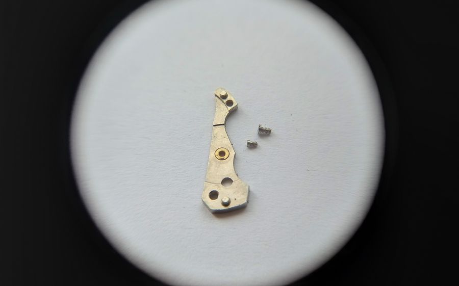
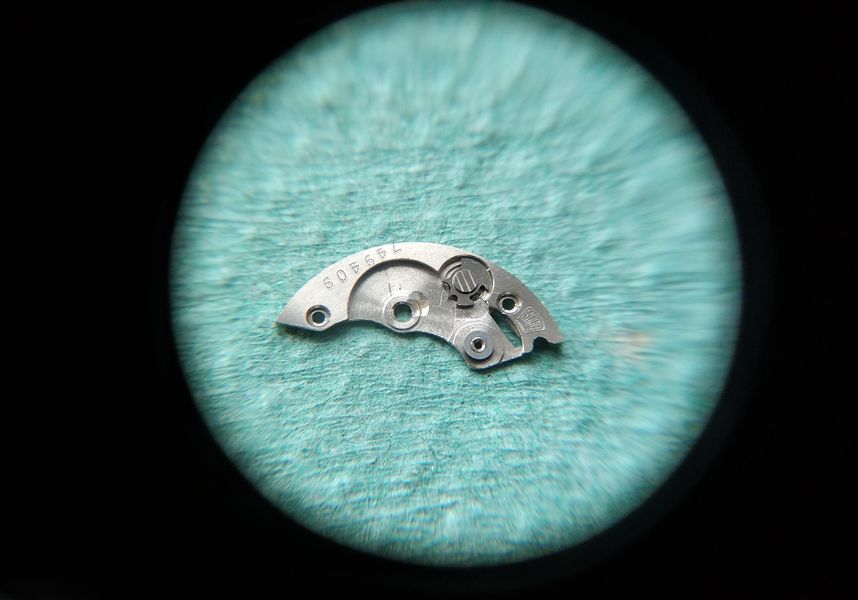
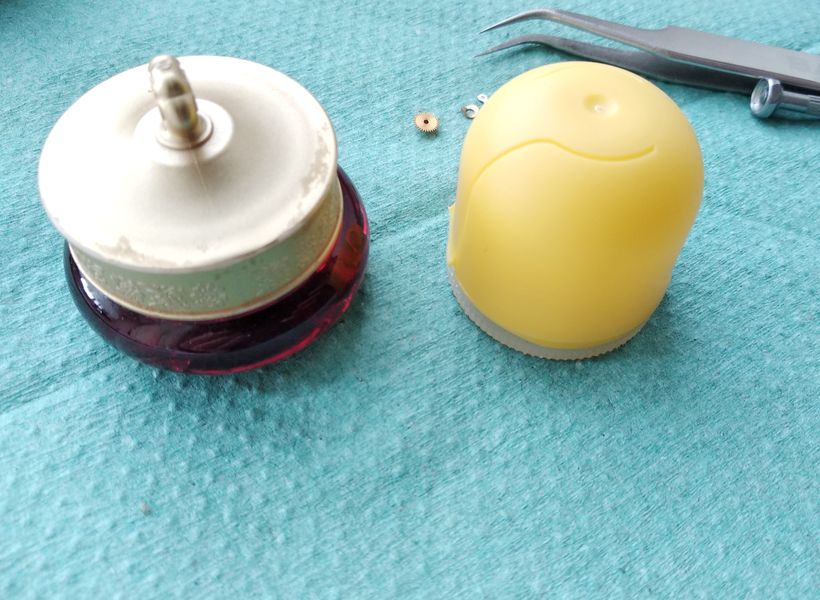
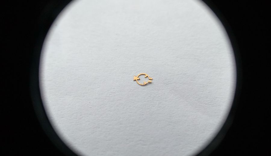
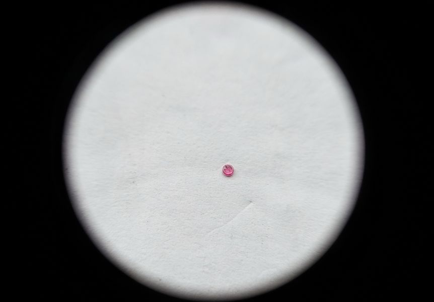
The retaining spring for the intermediate setting lever has snapped. There is no repairing a broken leaf of this kind; it has to be replaced. Fortunately, a small box on the shelf holds odds and ends accumulated over years. We will dig through it when reassembly comes around.

The broken retaining spring of the intermediate setting lever in the keyless works
The fault: the retaining spring that holds the intermediate setting lever has fractured. Only replacement will do.

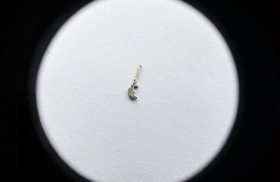
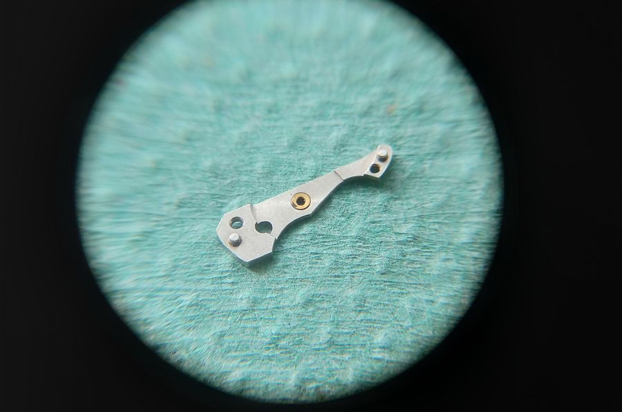
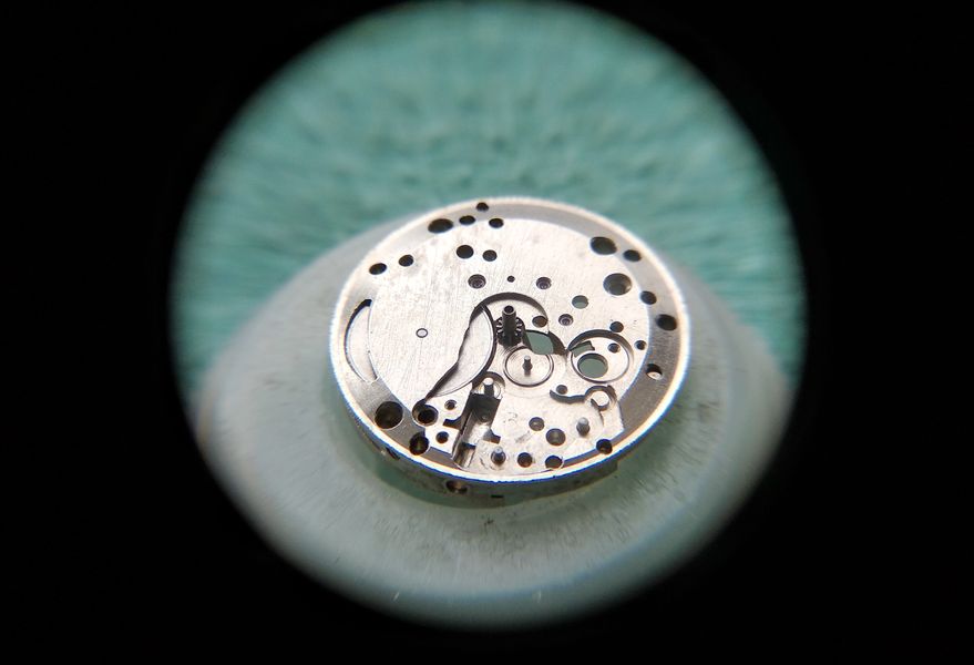
Here is the broken leaf itself, the snapped tongue of the spring.

Close-up of the fractured leaf of the setting-lever retaining spring
The broken leaf in close-up. A part this small carries no second chance — it either holds the lever or it does not.

Stripping the Slow Side

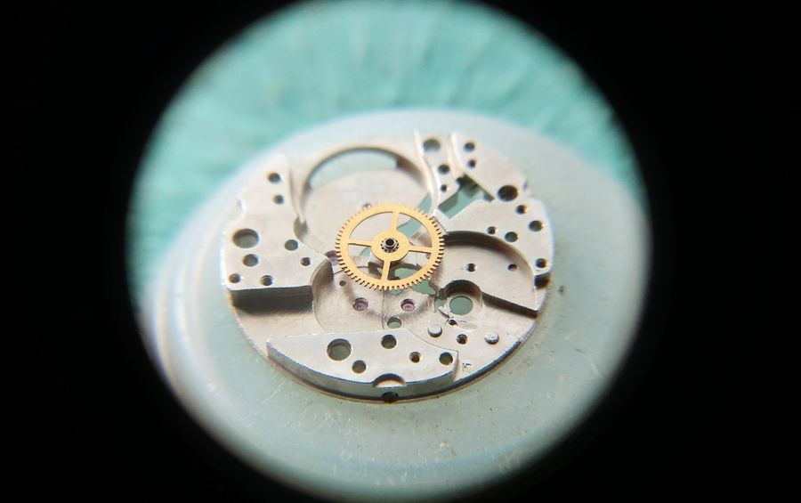
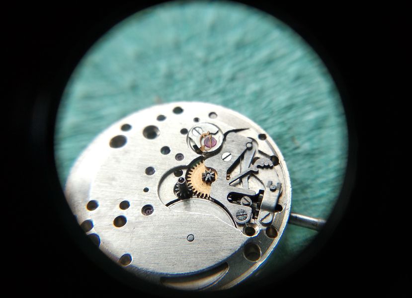
Since the movement is already lying dial-side up — the slow side, in workshop terms — that is where the teardown begins. First off is the hour wheel with its spring washer.

Hour wheel and its spring washer being removed from the dial side of the movement
The hour wheel lifts off together with its spring washer, the first component down on the motion-work side.

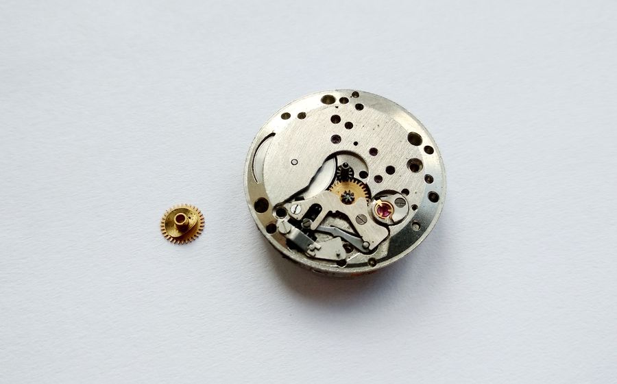
Next, without delay, the cannon pinion. This is the classic friction-fit arrangement — a cannon pinion gripping the center arbor by interference.

Friction-fit cannon pinion being pulled from the center arbor
The cannon pinion comes off next. It rides on the center arbor purely by friction — the textbook approach.

The Balance and Escapement

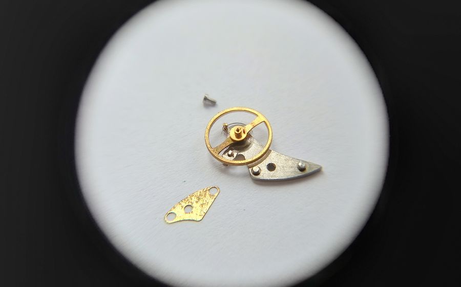
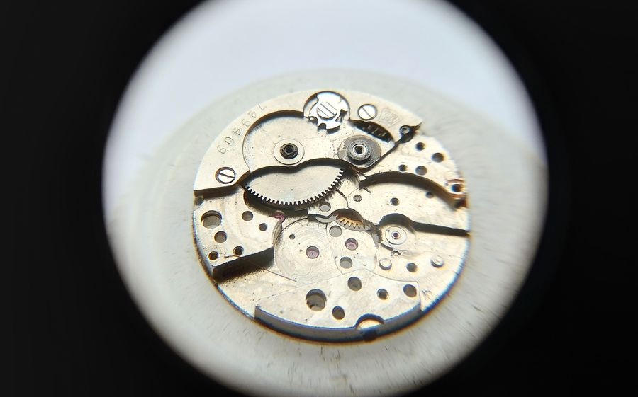
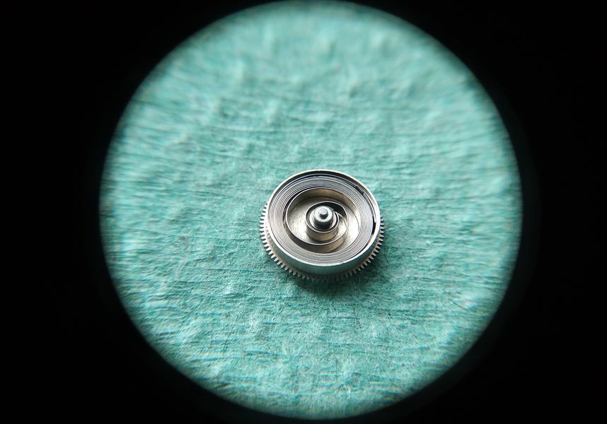
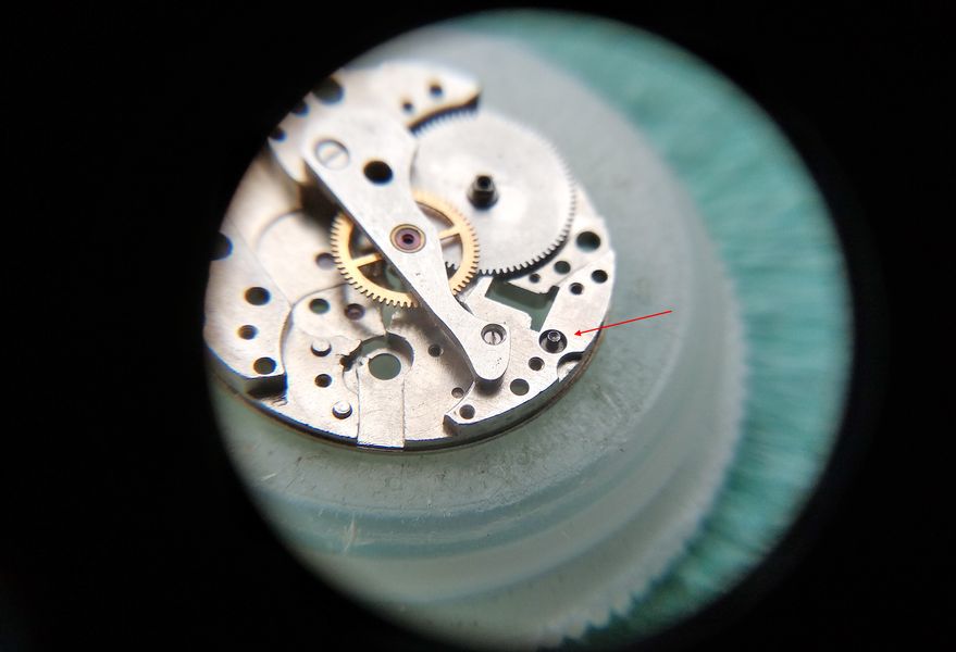
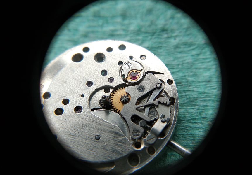
Now the movement is turned over to the bridge side, and the balance is lifted out.

Movement flipped to the bridge side with the balance and cock being removed
Flipped over, the balance assembly is the first thing to come away from the train side.

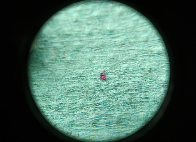
The balance is screwless. The stud carrier is fixed, the regulator is present with its pins captive at the index, and there is a gasket beneath the balance cock. What immediately draws the eye, though, is the unusual shape of the bushing spring. It is precisely this bushing construction that earned the movement its "08" classification under GOST — but the details will wait until we reach the bushing service, with a good deal of work still to do before then.

The screwless balance and its cock showing the fixed stud carrier, regulator, and the unusually shaped bushing spring
A screwless balance with a fixed stud carrier and a conventional index regulator. The oddly formed bushing spring on the cock is the detail that defines this caliber — more on it shortly.

The underside of the balance holds no surprises: a double roller, an ellipse for an impulse jewel, and the staff with its pivot.

Underside of the balance wheel showing the double roller, impulse jewel, staff and pivot
The reverse of the balance — double roller, the ellipse impulse jewel, and a clean staff and pivot. Entirely orthodox.

The pallet fork is equally conventional. Its bridge locates on two guide pins and is held by a single screw.

The pallet fork and its bridge, located on two guide pins and secured by one screw
A classic pallet fork. The cock seats on a pair of guide pins and is fixed with one screw — nothing exotic in the escapement itself.

Gear Train, Center Wheel, and Barrel

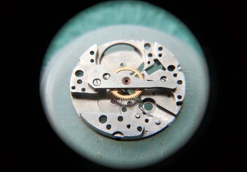
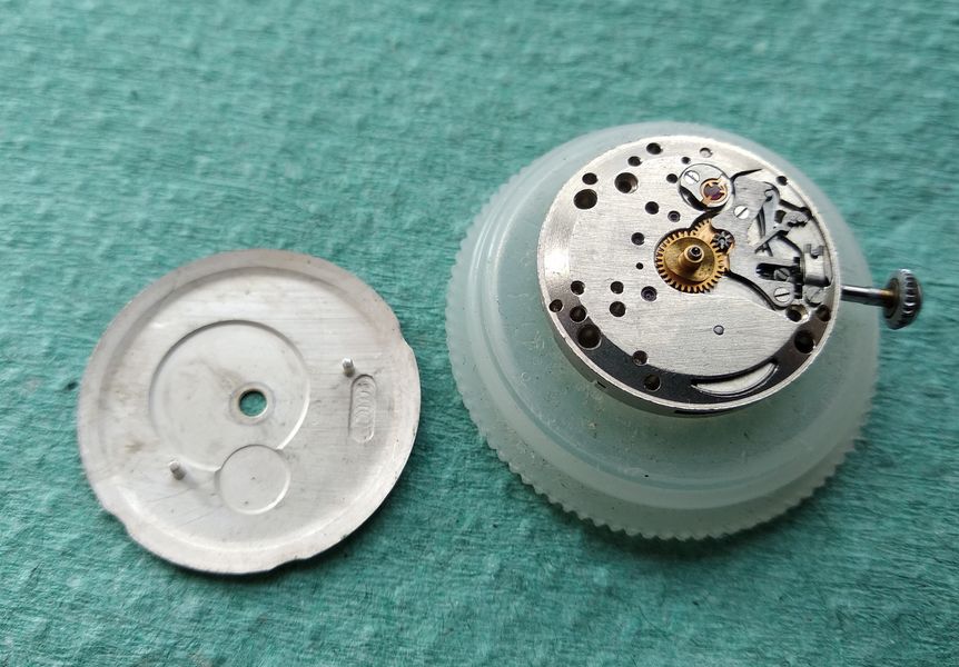
Now the train. The gear-train bridge comes off first. Because of the movement's multi-storey construction it sits high — the very feature responsible for the domed case back. With the bridge removed, the seconds, intermediate, and escape wheels lift out.

Gear-train bridge removed, exposing the seconds, intermediate and escape wheels
The tall gear-train bridge off, the running train exposed. Seconds, intermediate, and escape wheels all come away from here.

That leaves only the center-wheel bridge and the center wheel itself still in place.

Movement with only the center-wheel bridge and center wheel remaining
What remains: the center wheel under its own dedicated bridge, the last of the train to be addressed.

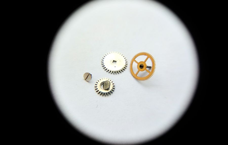
Here is the dismantled wheel set laid out together.

The disassembled train wheels laid out on the bench
The train wheels removed and set aside in order, ready for cleaning.

Next the center-wheel bridge. Seen from its inner face, it looks ordinary enough.

Inner face of the center-wheel bridge after removal
The center-wheel bridge, inner side. The interesting feature is on the other face.

Turn the bridge over and the construction of the center-wheel bearing reveals itself. The jewel is mounted in a dedicated chaton, which makes for a combined bearing: the wheel rests on a brass shoulder while its arbor turns in the jewel.

Outer face of the center-wheel bridge showing the jewel set in a chaton forming a combined bearing
From the outside, the center-wheel jewel sits in its own chaton. The result is a combined bearing — brass shoulder for support, jewel for the turning arbor.

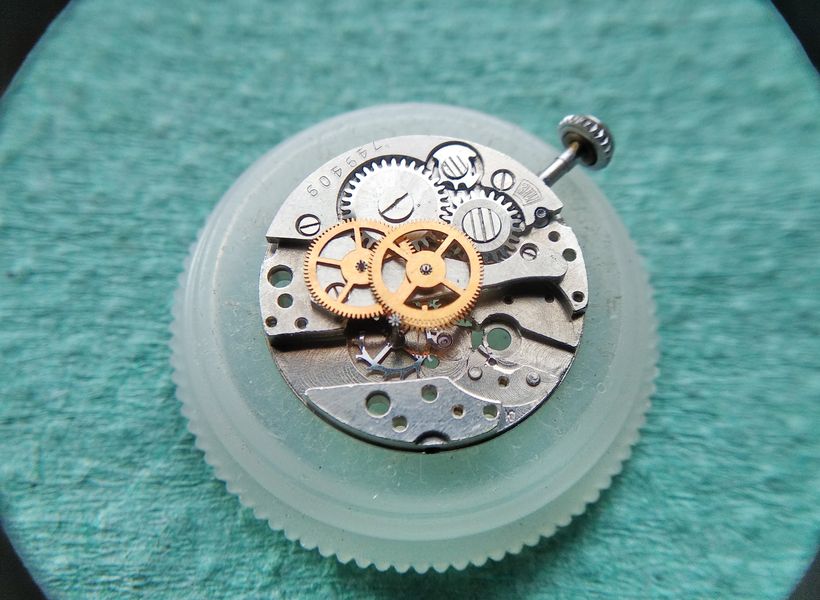
To get the center wheel out, the winding wheels of the mainspring motor have to come off first. In hindsight that should have preceded removing the center-wheel bridge, but no harm is done. Off come the winding wheels.

The winding wheels of the mainspring motor being removed from the plate
The winding wheels of the spring motor have to be cleared before the center wheel will release.

Now, at last, the center wheel can be lifted out.

The center wheel being lifted from the main plate
With the winding wheels gone, the center wheel finally comes free.

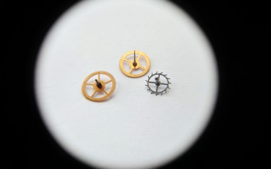
There they are together: the winding wheels and the center wheel.

The winding wheels and the center wheel removed and grouped together
The motor's winding wheels alongside the center wheel, all clear of the plate.

The barrel bridge, the barrel, and the barrel itself come next. The barrel lid is removed — but, to be honest, the mainspring is staying put. It will be cleaned in place.

The barrel opened with its lid removed, mainspring left in place inside
The barrel opened. The mainspring is left coiled inside and will simply be washed there rather than drawn out.

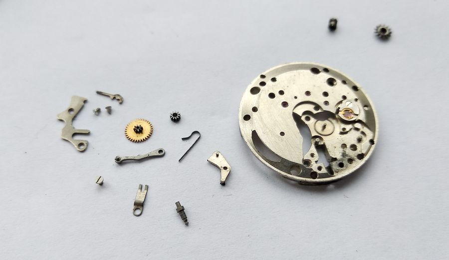
With the fast side stripped, the now-open window in the plate gives access to the sliding clutch and the winding pinion of the keyless works, which are drawn out.

The sliding clutch and winding pinion withdrawn through the opening in the plate
Through the freed window, the sliding clutch and winding pinion are extracted from the keyless works.

The keyless works is then fully taken apart. Here are its components; their arrangement on the plate will be shown during reassembly. There is no point photographing the parts grimy, and while we are in here the broken spring will be swapped for a sound one.

The disassembled keyless works components laid out beside the main plate
The keyless works broken down into its individual parts. Their placement will be demonstrated on reassembly, and the fractured spring replaced along the way.

The Removable Balance Bushings

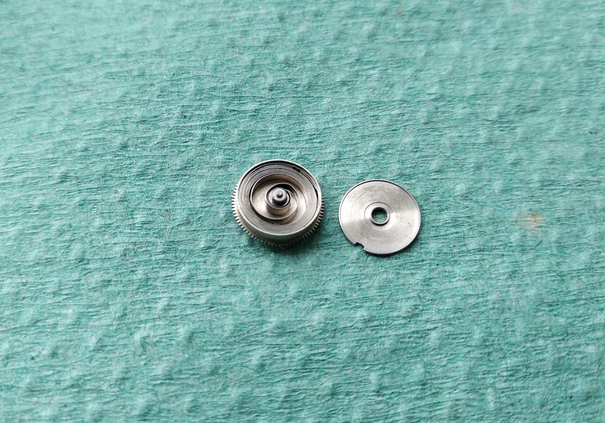
Now to the defining feature of this movement — the balance bushings. Here they are made removable. So we take the bushing off the plate and send it to soak, letting it sit in benzine to loosen the grime.

The removable balance bushing being detached from the main plate
The central peculiarity of the caliber: the balance bushing is a removable unit. Off it comes for a benzine soak.

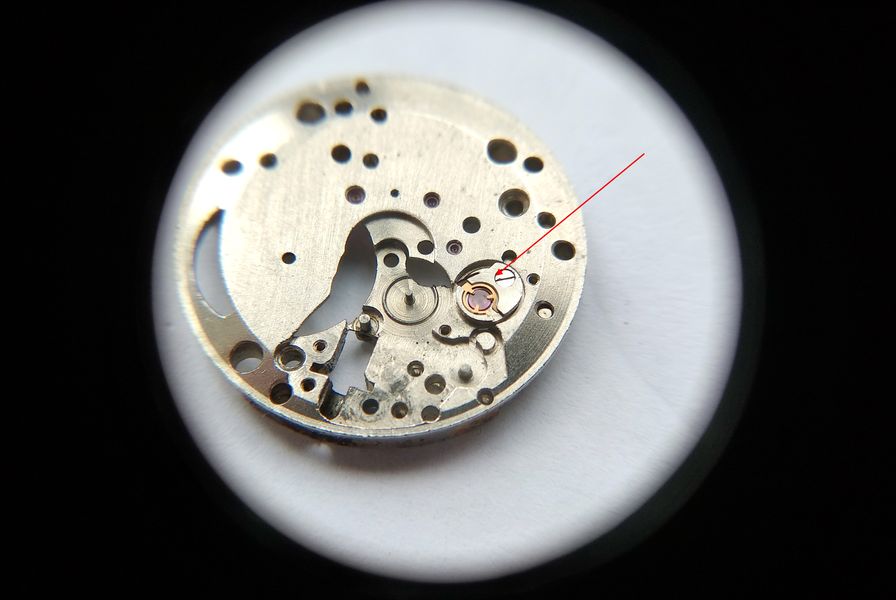
A single retaining screw frees it.

The retaining screw of the balance bushing being unscrewed to release the bushing
Out with the retaining screw, and the bushing lifts away from the plate.

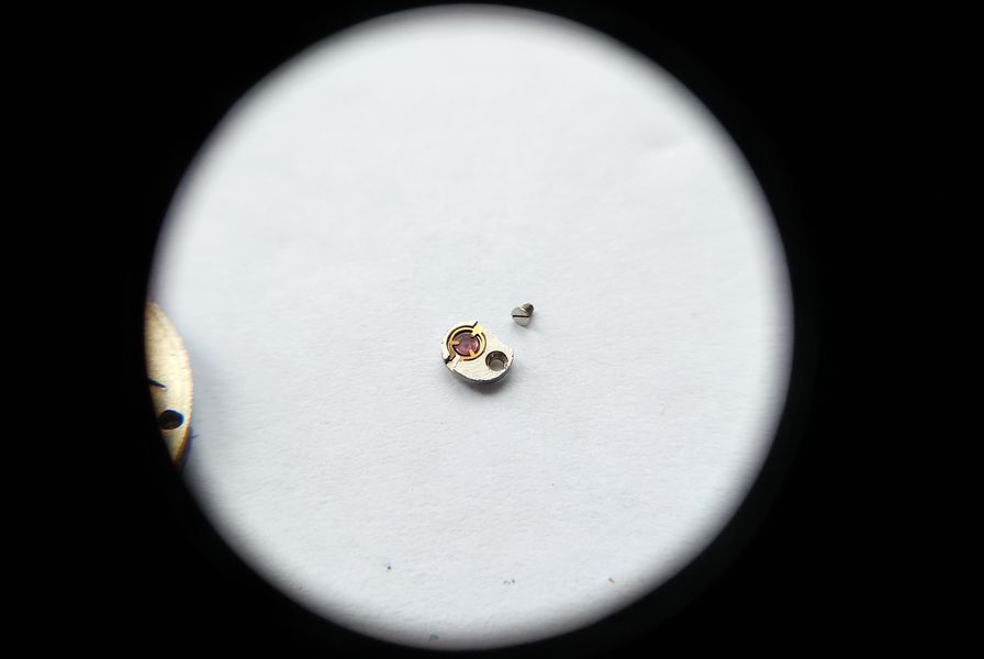
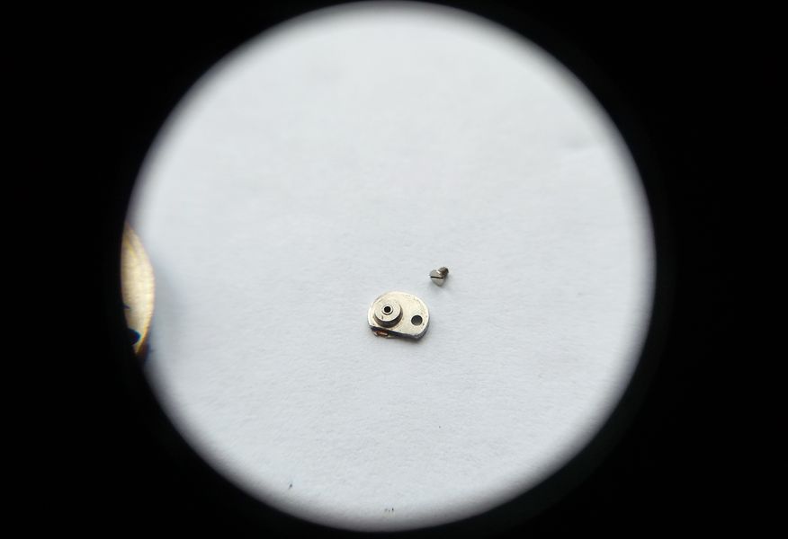
And this is its reverse face. It will be cleaned and then taken apart during installation, where its construction can be studied properly.

The reverse side of the removable balance bushing
The bushing seen from behind. We will dismantle it during reassembly to see exactly how it is built.

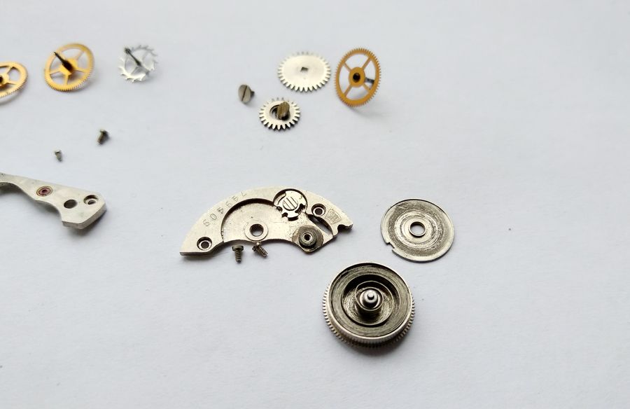
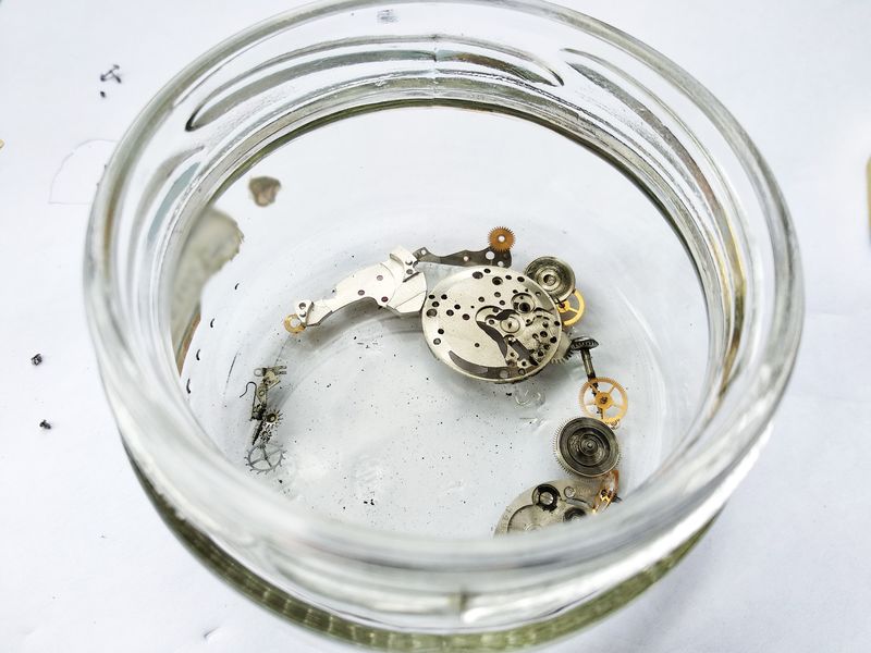
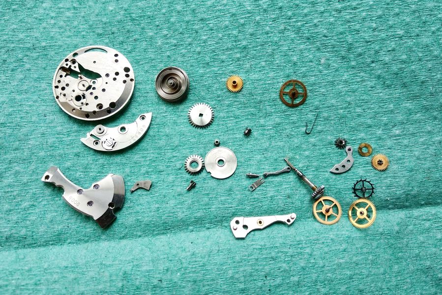
And so, to borrow and bend the words of a well-known Soviet children's song — what, then, is our Yunost made of? Here it all is, spread out.

The full set of disassembled movement components spread out on the bench
What is the Yunost made of? The answer, laid bare: every component of the caliber accounted for and ready for cleaning.

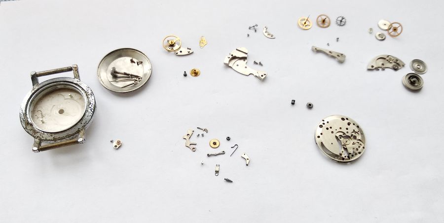
The parts are gathered and sent into benzine to soak. While they sit, the coffee maker is signaling — so a cup of coffee, then brushes and an old toothbrush will bring everything back to a respectable state.

Movement components collected together before going into a benzine bath for cleaning
Everything assembled for the benzine bath. A short pause for coffee while the solvent does its part.

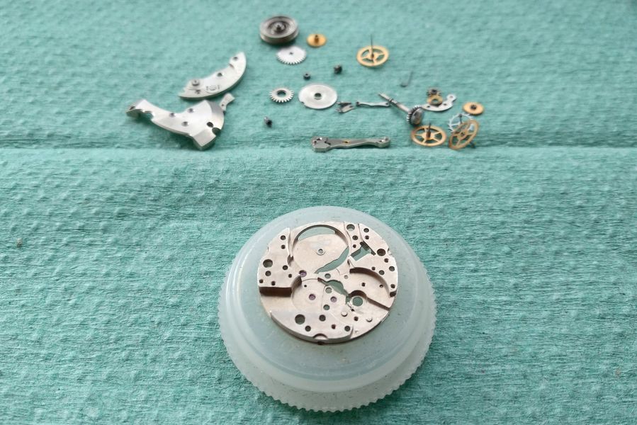
Coffee drunk, cleaning done, the parts are arranged on a blotter. We will try working on it.

All cleaned movement parts arranged on a green blotter ready for reassembly
The cleaned components laid out on a blotting pad. From here on it is reassembly, and the watchmaking proper begins.

Reassembly: Center Wheel and Barrel

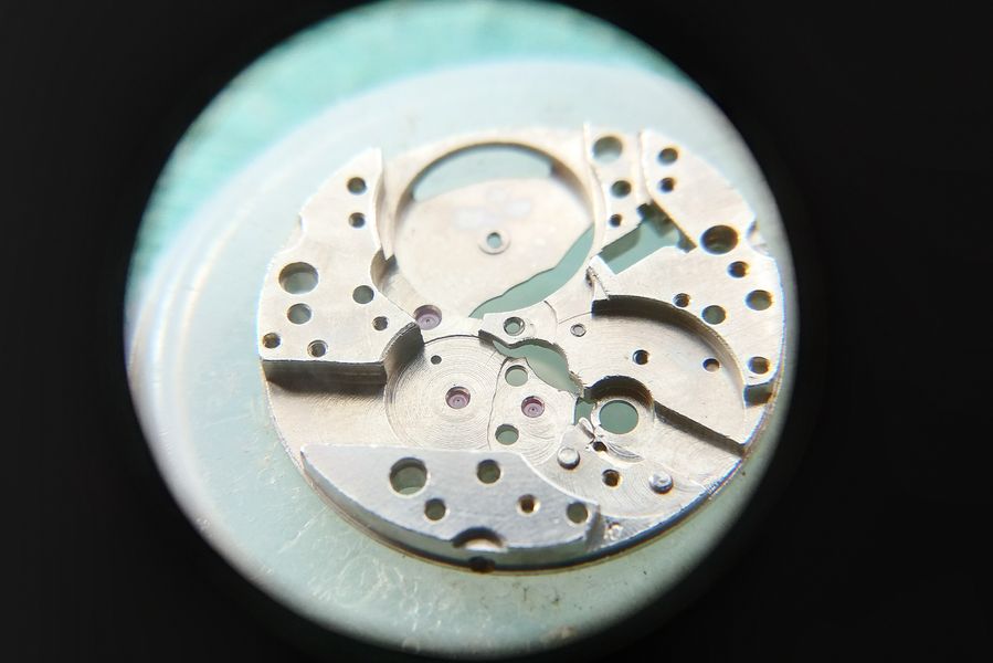
The main plate is prepared and set on its holder.

The bare cleaned main plate mounted on a movement holder ready for reassembly
The plate, cleaned and seated on its stand. The build starts here.

And we begin with the center-wheel assembly. As noted, there is no jewel under the center wheel — fifteen jewels in total. The closely related Zarya 2009 carries seventeen, but not because a jewel is added to the center arbor: that bearing is identical. The extra two jewels in the 2009 are cap jewels placed over the train's through-jewels on the plate side. Economy being what it was, there always had to be room left for "rationalization" and future improvement. So: a drop of oil into the hole for the center-wheel arbor.

The center wheel held in tweezers before installation
The center wheel, ready to go in. With no jewel beneath it, this most heavily loaded wheel runs in a plain bearing — one of the economies that keep the count at fifteen.

The center wheel goes onto the plate.

The center wheel being set into position on the main plate
The center wheel set down onto its oiled bearing in the plate.

The jewel of the center-wheel bridge is lubricated with MBP-12.

The center-wheel bridge jewel being lubricated with MBP-12 oil
A charge of MBP-12 on the chaton-set jewel of the center-wheel bridge.

The center-wheel bridge is fitted. The wheel turns freely. Excellent.

The center-wheel bridge installed over the center wheel
Bridge in place, the center wheel spinning with a light, free action — just as it should.

Now the barrel, washed and free of every trace of old grime. Look how clean it is. The mainspring is given several drops of precision-mechanism oil.

The cleaned barrel with the mainspring being lubricated with precision-mechanism oil
The barrel, scrubbed clean. The mainspring receives a few drops of precision-mechanism oil before the lid goes back on.

The barrel lid is pressed home.

The barrel lid being closed over the lubricated mainspring
Closing the barrel. The spring is sealed in with its fresh lubrication.

And the barrel is set on the plate, its arbor oiled beforehand. There are neither jewels nor hardened inserts in the plate or in the barrel bridge, but both carry substantial bosses — and so the seats show no wear.

The closed barrel being installed onto the main plate with the arbor oiled
The barrel goes down with its arbor oiled. Generous brass bosses, rather than jewels, carry the barrel — and they have held up without wear.

The seat in the barrel bridge is oiled.

The barrel bridge bearing seat being lubricated
Oil to the barrel-bridge seat — the upper bearing for the barrel arbor.

An important reminder before the barrel bridge goes on: do not forget to set the stem-release button of the keyless works in place.

The stem-release button being installed before the barrel bridge is fitted
A crucial step that is easy to miss — the stem-release button must be seated before the barrel bridge closes over it.

Now the barrel bridge is returned to its place and the train of winding wheels is installed. As a reminder, the crown wheel is secured by a left-hand-thread screw — note the three slots in its head. That is the one.

The barrel bridge fitted and the winding wheels installed, with the triple-slotted left-hand crown wheel screw indicated
Barrel bridge down, winding wheels set. The crown-wheel screw with three slots takes a left-hand thread — a detail worth committing to memory.

Reassembly: The Slow Side and Keyless Works

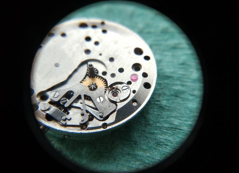
The movement is turned over and assembly of the slow side begins.

Loupe view of the assembled winding-wheel side of the movement as it is turned over for slow-side assembly
A loupe check of the freshly built barrel-bridge side before the movement is flipped to take on the motion work.

First on this side goes the cannon pinion, fitted before anything else so the minute wheel cannot be damaged later in the build.

The cannon pinion installed at the center of the dial-side plate
The cannon pinion seated at the center of the dial side — the first component down, and a guard against harming the minute wheel during the rest of the work.

Now the small setting wheel — and here there is a subtlety. Look at its end face. On this side it is perfectly flat, machined square at ninety degrees.

The small setting wheel showing its flat square-machined end face
The small setting wheel, flat face up — this side is cut square at ninety degrees.

On the other side that same face is machined at an angle, as a chamfer. Why? Because it is this chamfered edge that engages the teeth of the sliding clutch when the hands are set by hand. The setting wheel must therefore go in with the chamfered side facing the sliding clutch — which, in this movement, means facing down toward the plate. This, incidentally, holds true for most movements; it is a point I had long overlooked and never mentioned in earlier accounts.

The reverse of the small setting wheel showing its chamfered angled face
The reverse carries a chamfer. That bevel meshes with the sliding clutch during hand-setting, so it must face the clutch — here, downward toward the plate.

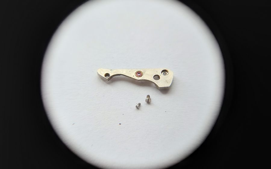
The keyless-works parts are returned to their places. Here is the assembly in the photograph. It only remains to lubricate it and cover it with its spring plate — and yes, a sound replacement plate was tracked down in the spares. It is remarkable what turns up when you scrape the bins and rummage the shelves.

The keyless works reassembled on the plate, ready to be oiled and covered
The keyless works rebuilt and laid out on the plate. Lubrication and the spring cover plate — a freshly found, unbroken one — come next.

And the keyless works is covered. With nothing more to do here for now, we move to the fast side to build up the train.

The keyless works covered by its spring retaining plate
The keyless works closed under its cover plate. Time to turn back to the train side.

Reassembly: The Going Train

What is left here is to set the train wheels, the gear-train bridge, the pallet fork, and the balance.

The train side of the movement awaiting installation of the wheels, bridge, pallet fork and balance
The fast side, ready to receive the going train and escapement.

The wheels go in starting with the escape wheel, then the intermediate wheel, and finally the seconds wheel.

The going-train wheels being installed, beginning with the escape wheel
The train laid in sequence — escape wheel first, then intermediate, then seconds.

The gear-train bridge is fitted over the train and the jewels are oiled.

The gear-train bridge installed over the wheels with the jewels being lubricated
The bridge caps the train, and each jewel receives its drop of oil.

A word on procedure here. Once the movement has been oiled it should not be left open for long, because dust will settle onto the lubricant — and that does no good at all. If the work has to be interrupted, the movement should be covered. For this I have pressed a Kinder-egg capsule into service; it fits just right. A short break, and we continue in half an hour.

A Kinder-egg plastic capsule used as a dust cover over the partly assembled oiled movement
An improvised dust cover — a Kinder-egg capsule — shields the freshly oiled movement during a pause in the work.

Continuing. First the run-down is checked, and it is superb — the train coasts back some twenty turns. Then the pallet fork is installed; the mainspring is wound a couple of turns and the impulse tested by nudging the fork, which should snap smartly to its banking on its own. The impulse is checked in both directions. All good.

The pallet fork installed and the going train being tested for free run-down and impulse
Pallet fork in place. The train coasts freely through some twenty revolutions, and the fork snaps crisply to its banking on both sides — the escapement is alive.

The Bushings Explained, and the Balance Refitted

And so to the bushing. First it is set on the plate and secured with its screw.

The lower balance bushing being installed on the plate and fixed with its screw
The lower bushing returns to the plate, held by its single screw, ready for servicing.

Now the spring that retains the cap jewel is swung aside. As you can see, it is captured in its frame and will not fall out as you work.

The cap-jewel retaining spring of the bushing being swung open while remaining captive in its frame
The retaining spring opens to one side. It stays captive in the bushing frame — there is no loose spring to lose.

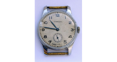
Out comes the cap jewel. There — and now look closely at how this differs from the Incabloc of the "09" calibers. In an Incabloc, the block is autonomous, with every degree of freedom: the through-jewel and cap jewel sit together in a separate chaton that can shift within its seat. In this movement — the 2008 — the through-jewel is fixed rigidly, and only the cap jewel sits under the spring. That places the design in an intermediate position between a fully shock-protected balance and an unprotected one. Vertical displacement of the balance is absorbed to some degree; lateral displacement is not. But the arrangement should, in principle, prevent the "mushrooming" peen on the balance pivot — that classic ailment of the Pobeda, the Molnija, and their kin. Hence the "08." A step forward all the same.

The cap jewel removed from the bushing, exposing the rigidly fixed through-jewel beneath
The cap jewel lifted out. Beneath it the through-jewel is set rigidly — only the cap jewel is sprung. This half-measure damps vertical shock and, crucially, guards against the mushroom peen that plagues unprotected staffs.

Carrying on, the cap jewel is oiled. The rule was stated earlier — a droplet covering sixty to seventy percent of the surface.

The cap jewel of the bushing being lubricated with a measured droplet of oil
Oiling the cap jewel — a drop sized to cover roughly two-thirds of the surface, neither flooding nor starving it.

Let us look at the bushing spring more closely. The small ears by which it is anchored are clearly visible. These ears act as pivots: the spring swings open on them to give access to the cap jewel, yet never parts company with the bushing.

Close-up of the bushing spring showing the small ears that act as pivots
The bushing spring in detail. The little ears serve as hinges, letting the spring swing aside without ever escaping the frame — a neat answer to a fiddly problem.

Done. The unit is serviced. The balance can go in.

The lower bushing closed and serviced, ready for the balance to be fitted
Lower bushing serviced and buttoned up. Time to seat the balance.

With the balance installed, the same procedure is repeated on the upper bushing. Open the spring.

The balance refitted and the upper bushing spring being opened for service
Balance in place. The upper bushing now gets the identical treatment — spring swung open.

The cap jewel is cleaned and oiled.

The upper cap jewel being cleaned and lubricated
The upper cap jewel cleaned and charged with oil, to the same measure as the lower.

The through-jewel hides down in its seat; the oiled cap jewel is returned over it.

The oiled cap jewel being replaced over the through-jewel in the upper bushing seat
The cap jewel goes back over the through-jewel seated below it, completing the upper bushing.

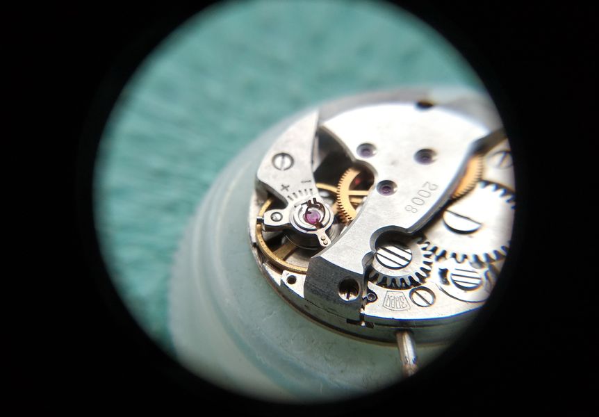
Done — and the watch is running.

The fully assembled movement running on the bench
Both bushings serviced, balance oscillating — the movement is alive and ticking.

Casing Up

Now the "trim." The cleaned dial is fitted back onto the movement.

The cleaned silvered dial being refitted onto the running movement
The cleaned, silvered dial returns to the movement.

Like so.

The dial seated on the movement, dial feet secured
Dial seated and secured, the face once again presentable.

The hands are set back in place.

The hour, minute and seconds hands being refitted to the dial
Hands refitted — hour, minute, and the central seconds that define the caliber.

As for the case, there is no bringing it to wearable condition at home. It has been cleaned as far as that is possible. But as a curiosity — a movement unlike the others — it is perfectly suited to a collection. Not many people, I suspect, know about these little tricks of the trade.

The cleaned but heavily worn chrome case after restoration attempts
The case, cleaned as far as home means allow. The plating is past saving, but as a study piece the watch earns its place.

The movement is installed back into the case.

The serviced movement being lowered back into the watch case
The serviced movement goes home into its case.

The crystal, for its part, polished out nicely.

The acrylic crystal after polishing, now clear
The acrylic crystal came up clear and bright after polishing — a worthwhile bit of work.

The case back is snapped closed.

The domed case back being pressed closed over the movement
The convex back snaps home over the humpbacked movement.

Like this.

The closed case back of the reassembled watch
Closed and sealed, the domed profile once again on display.

And here is the flat on the crystal bezel — far easier to make out now that the case has been cleaned.

The flat on the crystal bezel clearly visible after the case has been cleaned
The bezel flat, much clearer against the cleaned case — that deliberate facet tucked beneath the lug.

And that is all.

Detail of the finished watch after servicing and cleaning
The finishing detail, the work complete.

An ordinary youth's watch, then — and an extraordinarily instructive one. The Yunost on the Zarya 2008 looks like nothing special, yet it preserves a genuine moment in the history of Soviet horological engineering: the cautious, half-step solution to shock protection, captured in a removable bushing with a captive cap-jewel spring. The factories would soon resolve the question fully with the Incabloc-equipped "09" calibers, but the logic is all here on the bench, plain to read. Ah, the Yunost.

The fully restored Yunost wristwatch, serviced and reassembled
The finished Yunost — modest, well worn, and quietly remarkable in what it taught along the way.
0
2
4 June, 2026
New
Soviet Watch Zarya Wrist Mechanical Gold Plated Watch New Bracelet Made in USSR 1975
Model: SWZ01
Out Of Stock
$120.00
Comments0

Write a review

Note: HTML is not translated!
icon_whatsapp icon_mes icon_teleg icon_email icon_viber icon_callback